CSC/ECE 506 Spring 2010/ch 12 PP
Interconnection Networks
Choosing the “Best” Network
While there is no best network that would work well for all applications, it greatly depends on the given application and the parallel system at hand. The following are some of the factors affect the choice of interconnection network.
1. Performance Requirements: Minimize message latency, avoid network from saturating (unable to deliver messages injected by nodes) and increase throughput of the network.
2. Scalability: Adding more processors should increase I/O bandwidth, Memory Bandwidth and Network Bandwidth should increase proportionally.
3. Incremental expandability: Should provide incremental expandability, allowing addition of a small number of nodes while minimizing resource wastage. For example, a network designed for number of processors to be a power of 4 makes it difficult to expand.
4. Partitionability: May be required for security reasons. If network can be partitioned into smaller systems, traffic produced by one user will not affect the others.
5. Simplicity: Simple Design lead to higher clock frequencies and better performance.
6. Distance Span: Maximum distance between nodes should be small.
7. Physical Constraints: Complexity of the connection is limited by the maximum wire density possible and by the maximum pin count. Factors like packaging, wiring, operating temperature should be taken into account since they pose many limitations on designs.
8. Reliability and Reparability: Should allow easy upgrades and repairs. Should minimize faults or detect them and correct them.
9. Expected Workloads: If kind of application is known in advance, network can be optimized for it. If not, network should be robust, design paramenters should be selected to perform well over a wide range of traffic conditions.
10. Cost Constraints: The “best” network might be too expensive. Alternative design considerations are important to meet cost constraints.
Classification of Interconnection networks
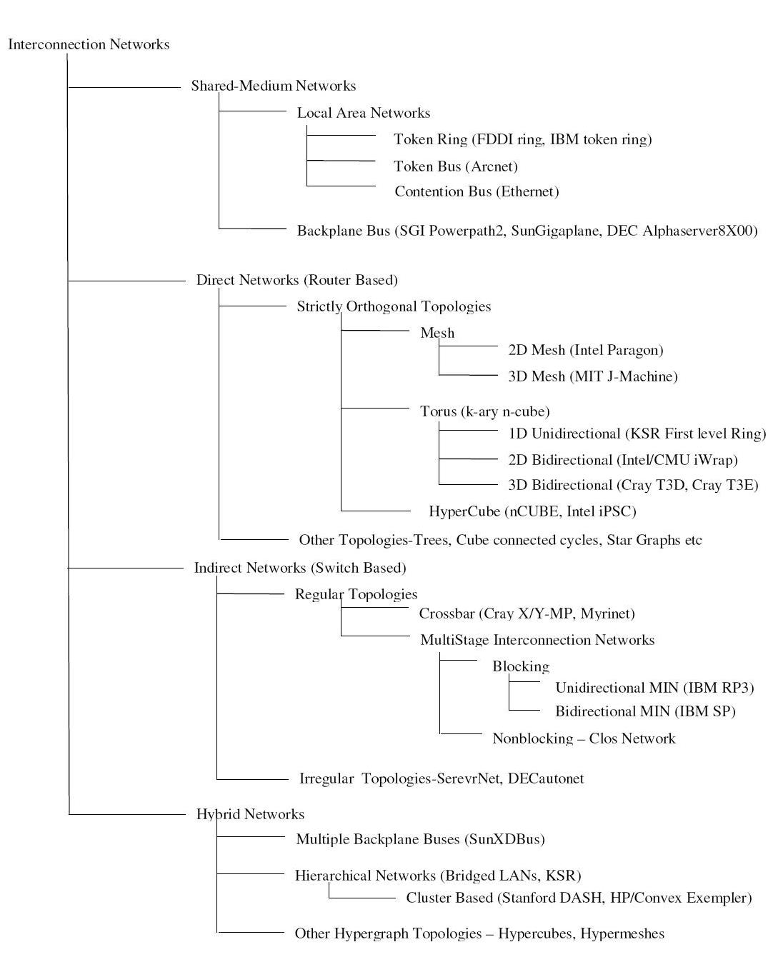
Figure 1 classifies Interconnection Networks based on network topologies. For each class, figure shows hierarchy of subclasses with some real implementations in parenthesis. In Shared-Medium Networks, transmission medium is shared by all devices. Direct Networks have point to point links directly connecting each communicating device to a subset of other devices in the network. Indirect networks connect devices using one or more switches. Hybrid networks are a combination of the above approaches.
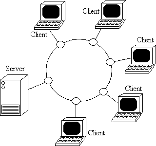
Token Ring
Implementation examples:
- IBM token ring: Supports bandwidth of 4 or 16 Mbps based on coaxial tube
- FDDI: Bandwidth of 100Mbps using fiber optics
Token Bus
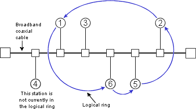
Nodes are physically connected as a bus, but logically form a ring with tokens passed around to determine the turns for sending. A token is passed around the network nodes and only the node possessing the token may transmit. If a node doesn't have anything to send, the token is passed on to the next node on the virtual ring.
Implementation examples:
- ARCNET: Attached Resource Computer NETwork
Backplane Bus
Simplest interconnection structure for bus-based parallel computers. Commonly used to connect processors and memory modules to form UMA architecture. Many techniques are used for information transfers like synchronous, asynchronous, multiplexed and non-multiplexed.
Implementation examples:
- Gigaplane used in Sun Ultra Enterprise X000 Server (ca. 1996): 2.68 Gbyte/s peak, 256 bits data, 42 bits address, split transaction protocol, 83.8 MHz clock
- DEC AlphaServer8X00, i.e. 8200 & 8400 (ca. 1995): 2.1 Gbyte/s, 256 bits data, 40 bits address, split transaction protocol, 100 MHz clock (1 foot length)
- SGI PowerPath -2 (ca. 1993): 1.2 Gbyte/s, 256 bits data, 40 bits address, 6 bits control, split transaction protocol, 47.5 MHz clock
- HP9000 Multiprocessor Memory Bus (ca. 1993): 1Gbyte/s, 128 buts data, 64 bit address, 13 inches, pipelined bus, 60 MHz clock
Direct Networks
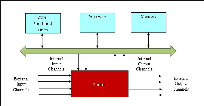
Bus based systems are not scalable since bus becomes a bottleneck when more processors are added. Direct network or point-to-point network scales well with large number of processors. A direct network consists of a set of nodes, each directly connected to a subset of other nodes. Figure__ shows a generic node.
Each Router is connected to its neighbor’s routers through a unidirectional or bidirectional channel and handles the message communication among nodes. Internal channels connect local memory/processor to the router. External channels are used for communication between the routers. A direct network is formed by connecting input channels of one node to output channels of other nodes. Every input channel is paired with a corresponding output channel and there are many ways to interconnect these nodes such that every node in the network is able to reach every other node.
Network topology is Orthogonal if and only if nodes can be arranged in a orthogonal n-dimensional space, and every link can be arranged in such a way that it produces a displacement in a single dimension.
Strictly Orthogonal Topologies
In a strictly orthogonal topology, every node has at least one link crossing each dimension.
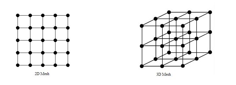
Mesh
Implementation Examples:
- Intel Paragon: 16 rows and 16 columns of nodes, with a 2D mesh connecting them, 130 MB/sec for 1 MB messages, with a latency of around 100 usecs.
- MIT Reliable Router: 2-D Mesh, 23-bit links (16- bit data), 200 MHz, 400 M bytes/s per link per direction, bidirectional signaling, reliable transmission.
- MIT M-Machine: 3-D Mesh, 800 M bytes/s for each network channel.
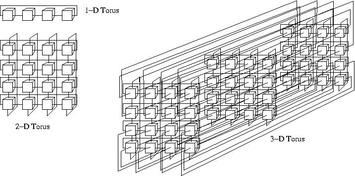
Torus
Implementation Examples:
- Chaos Router: 2-D torus topology, bidirectional 8-bit links, 180 MHz, 260 Mbytes/s in each direction.
- Cray T3E: Bidirectional 3-D torus, 14-bit data in each direction, 375 MHz link speed, 600 Mbytes/s in each direction.
- Cray T3D: Bidirectional 3-D torus, up to 1024 nodes (8 x 16 x 8), 24-bit links (16-bit data, 8-bit control), 150 MHz, 300 Mbytes/s per link.
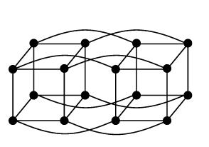
Hypercube
Implementation Examples:
- Intel iPSC-2 Hypercube: Binary hypercube topology, bit-serial channels at 2.8 Mbytes/s.
Other Topologies
In a Weakly Orthogonal topology, some nodes may not have any link in some dimensions.
Tree
Tree has a root node connected to a certain number of descendant nodes. A node with no descendants is a leaf node. If the distance from every node to the root is same, tree is balanced.
Disadvantage of this structure is that network is entirely dependent on the trunk which is the main backbone of the network. If that has to fail then the entire network would fail. Also, it gets difficult to configure after a certain point.
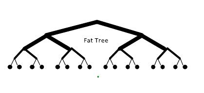
Fat Tree, unlike the normal tree, which has "skinny" links all over, the links become "fatter" as one moves up the tree towards the root. By judiciously choosing the fatness of links, the network can be tailored to efficiently use any bandwidth.
Cube-Connected Cycles
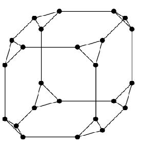
Cube-Connected cycles can be considered as an n-dimensional hypercube of virtual nodes, where each node is a ring with n nodes, for a total of n2^n nodes.
de Bruijn and Star Graph Networks
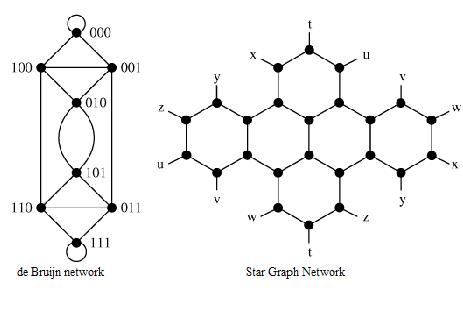
De Bruijn and Star Graphs are two well known topologies proposed to minimize the network diameter for a given number of nodes and node degree.
Indirect Networks
Indirect networks do not provide a direct connection among nodes; instead communication has to be carried out through switches. Each node has a network adapter that connects to a network switch. Regular topologies have a regular connection pattern between switches whereas irregular topologies do not follow ant predefined pattern.
Regular Topologies
Crossbar Network
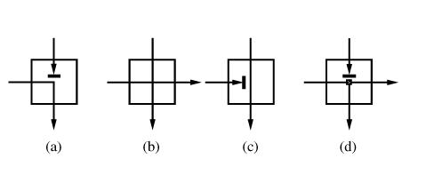
Crossbar networks allow many processors to communicate simultaneously without contention. It can be defined as a switching network with N inputs and M outputs, which allows up to min{N,M} one-to-one interconnections without contention.
Each switch point for a crossbar with distributed control can have four states as shown in Figure __. (a) shows that input from the row containing the switch has been granted access to the output while input from the upper row requesting the same output has been blocked. (b) shows that both inputs have been granted access since they requested different outputs. (c) shows that the upper input has been grated access and the same row input is blocked. (d) is required if multicasting (one-to-many communication) is supported.
Multistage Interconnection Network
Multistage interconnection networks (MINs) connect devices through a number of switch stages, where each switch is a crossbar network. They number of stages and connection patterns determine the routing capacity.
Figure below shows a generic MIN with N inputs, M outputs and g stages.
MINs can be divided into 3 categories depending on the availability of paths:
- Blocking: A connection between a free input/output is not always possible because of conlicts with the existing connections. But, multiple paths are provided to reduce conflicts and increase fault tolerance.
- Nonblocking: Any input port can be connected to any free output port without affecting the existing connections.
- Rearrangeable: Any input port can be connected to any free output port. However, existing connections mat require rearrangement of paths.
Depending on the kind of channels and switches, MINs can be divided into two classes: Unidirectional MINs and Bidirectional MINs.
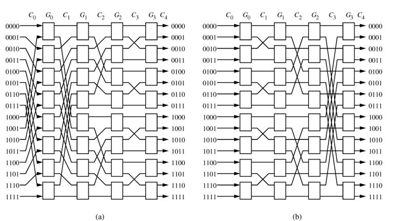
Figures below shows 4 unidirectional MINs. They differ in connection patterns.
Two 16 x 16 unidirectional multistage interconnection networks: (a) Baseline Network (b) Butterfly Network
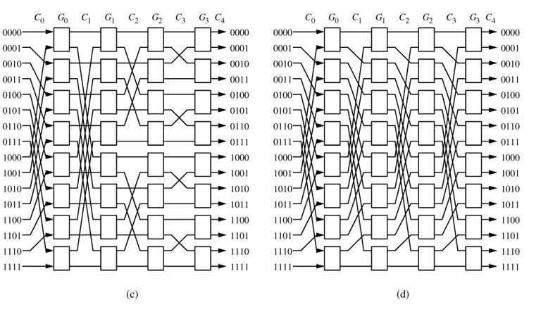 Two 16 x 16 unidirectional multistage interconnection networks: (a) Cube Network (b) Omega Network
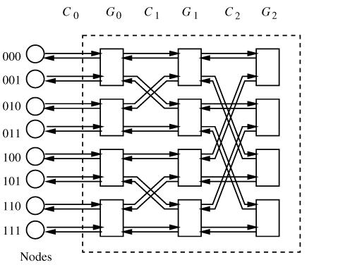
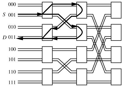
Following figures show an 8-node bidirectional butterfly MIN and alternate paths in the same.
Implementation examples of Indirect Networks:
- Myricom Myrinet: Supports regular and irregular topologies, 8 x 8 crossbar switch, 9-bit channels, full-duplex, 160 Mbytes/s per link.
- Thinking Machines CM-5: Fat tree topology, 4-bit bidirectional channels at 40 MHz, aggregate bandwidth in each direction of 20 Mbytes/s.
- Inmos C104: Supports regular and irregular topologies, 32 x 32 crossbar switch, serial links, 100 Mbits/s per link.
- IBM SP2: Crossbar switches supporting Omega network topologies with bidirectional, 16-bit channels at 150 MHz, 300 Mbytes/s in each direction.
- SGI SPIDER: Router with 20-bit bidirectional channels operating on both edges, 200 MHz clock aggregate row data rate of 1Gbyte/s. Offers support for configurations as nonblocking multistage network topologies as well as irregular topologies.
- Tandem ServerNet: Irregular topologies, 8-bit bidirectional channels at 50 MHz, 50 Mbytes/s link
