CSC/ECE 506 Spring 2013/2b so
Data Parallelism in GPUs
This article gives an overview of (Graphics Processor Unit) GPU’s and GPU architecture. It defines data parallelism in general. Finally it looks at how data parallelism is supported by GPU’s. This part of the topic is considered by having an overview of the various libraries
GPUs
General Processing Units (GPU) are processing units that help the Central Processing Unit (CPU) in a variety of calculations. In today’s graphic intensive applications, having a GPU along with a CPU is a norm. Having a GPU provides a very significant speed up in the performance of the application running on the CPU. The CPU offloads the computationally intensive portion of the application to the GPU. While the CPU consists of a few processors optimized for serial execution of code, the GPU consists of thousands of processors boosted for parallel execution of code.
Overview of GPU architecture
To get a good overview of GPU architecture, we shall look at the various architectures supported by multiple vendors. The following figure compares Cayman and Cypress architecture (supported by AMD) and Fermi architecture (supported by NVidia).
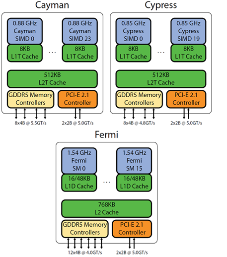
A typical GPU will consist of arrays of processing elements (PE’s). Now, while describing this array, the terminology varies from manufacturer to manufacturer. AMD considers the array as a SIMD core. For example, in the Cayman architecture, there are 24 SIMD cores, each consisting of 16 rows X 4 columns processing elements making the total number of processing elements equal to 1536. On the other hand NVidia considers the array to be streaming multiprocessor (SM) units. The Fermi architecture illustrated by Figure 1.1 has 16 SM’s, each containing 32 processing units. Each unit (SIMD or SM) will have its own memory (L1 cache) shared between the constituent PE’s and have access to the L2 cache. The unit will also have its own scheduler. The GPU will have a memory controller to interface external memory for the unit. The GGDR5 memory controller can support DDR3 RAM. The GPU will be interfaced with the CPU via a PCI controller.
Data parallelism
Parallel execution of code is defined as distributing the computation of code amongst the parallel processing elements (PE’s). There are various levels at which we can exploit parallelism which include bit, instruction, data and task level parallelism. Data parallelism (also called as loop level parallelism) is a type of parallelism where the data is distributed among the P.E’s. Here, the PE’s perform the same task on different subsets of data.
Example of data parallelism
for (i = 0; i<N; i++)
{
  a[i] = b[i] + c[i];
}
This is a highly simplified example of a code that can support data parallelism. Here, the array a[] contains the sum of arrays b[] and c[]. If we have N PE’s, we can allocate the computation of each element in array a[] to a processing element. In practice however, data dependencies exist that prevent data parallelism.
CUDA
CUDA is a parallel computing platform and a programming model created by NVidia supported by the GPU’s produced by them. Using CUDA, GPU’s are accessible for computations. The CUDA platform is accessible via CUDA libraries, compiler directives and extensions to C/C++ languages. CUDA also supports other interfaces such as OpenCL etc.
Data parallelism in CUDA: Example of a vector sum on a GPU using CUDA C
The following code illustrates data parallelism in a GPU by using CUDA C. CUDA C is an extension to C language. In CUDA C parallel execution of code is implemented by defining the code as a parallel kernel. This kernel is similar to a function in C except that it executes the code in parallel on N processors by creating N threads. Thread management in CUDA is shown below.
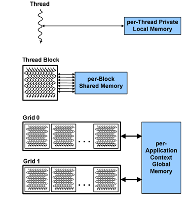
Each thread has its own private local memory. A set of threads which are running together are clustered in a block. The arrangement of threads in the block can be 2D or 3D with methods to access threads in both types of blocks. All threads in a block have access to a shared memory local to that particular block . Blocks in turn a can be arranged in a grid. All grids can access the application context global memory, which is global memory allocated per application.
#include "../common/book.h"
#define N 10
// add function
//__global__ denotes parallel kernel.
__global__ void add ( int*a, int*b, int*c ) {
int tid = blockIdx.x;  // handle the data at this index
if (tid < N)
c[tid] = a[tid] + b[tid];
}
int main( void)
{
int a[N], b[N], c[N];
int *dev_a, *dev_b, *dev_c;

// allocate the memory on the GPU
HANDLE_ERROR( cudaMalloc( (void**)&dev_a, N * sizeof(int) ) );
HANDLE_ERROR( cudaMalloc( (void**)&dev_b, N * sizeof(int) ) );
HANDLE_ERROR( cudaMalloc( (void**)&dev_c, N * sizeof(int) ) );

// fill the arrays 'a' and 'b' on the CPU
for(int i=0; i<N; i++) {
a[i] = -i;
b[i] = i * i;
}
// copy the arrays 'a' and 'b' to the GPU
HANDLE_ERROR( cudaMemcpy( dev_a, a, N * sizeof(int),cudaMemcpyHostToDevice ) );
HANDLE_ERROR( cudaMemcpy( dev_b, b, N * sizeof(int),cudaMemcpyHostToDevice ) );

add<<<N,1>>>( dev_a, dev_b, dev_c ); //N denotes the number of threads to execute.

// copy the array 'c' back from the GPU to the CPU
HANDLE_ERROR( cudaMemcpy( c, dev_c, N * sizeof(int),cudaMemcpyDeviceToHost ) );

// display the results
for(int i=0; i<N; i++) {
printf( "%d + %d = %d\n", a[i], b[i], c[i] );
}

// free the memory allocated on the GPU
cudaFree( dev_a );
cudaFree( dev_b );
cudaFree( dev_c );
return 0;
}
The above code takes the sum of 2 arrays and stores the result in the third array. Before beginning computations on the GPU, we need to allocate memory on the GPU corresponding to the 3 arrays using (cudaMalloc) and copy the data in the 2 arrays using (cudaMemcpy). The function add which actually does the addition has a directive __global__ to denote that it is a parallel kernel. The syntax << N, 1>> creates N threads corresponding to the kernel. The important part in add function is blockId.x. This is a built-in variable of CUDA which is available at runtime. This variable basically contains the id of the block in the GPU which is running the routine.
OpenGL
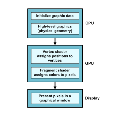
OpenGL (Open Graphics Library) is one of the most popular toolsets available for graphical processing, and many computer games and CAD tools rely on it for 3-Drendering. Originally developed by Silicon Graphics in the early 1990s, OpenGL has been ported to Windows, Linux, Mac OS. It is supported by NVidia and AMD on their GPU’s. On desktop computers, a modern OpenGL application consists of two parts: a host application that runs on the CPU and special-purpose routines called shaders that execute on the graphics processing unit, or GPU. In general, the CPU handles complex graphical routines such as physics and geometry and the GPU performs simple tasks like assigning positions to vertices and colors to pixels. Figure 1.3 depicts the relationship between the host and the shaders in an OpenGL application.
The graphics pipeline of OpenGL
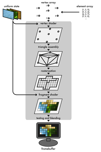
The graphics pipeline is a sequence followed for rendering an image on the screen (frame buffer). Here, the scene which is to be rendered contains multiple vertices arranged in an array. The attributes of these vertices are stored in a vertex buffer. Attributes include the position of the vertex in the real world, etc. These attributes are given to a vertex shader. This shader maps all the vertices in 3D space. A vertex shader can also assign some color information to the vertices. The triangle assembly module connects the vertices to form triangles. The rasterization module converts the triangles into discrete regions consisting of pixels. If the vertices contained color data, this data will be filled in the discrete regions enclosed the boundaries that were previously the edges of the triangles. The fragment shader combines the data from the rasterization module as well as the uniform data which is passed to the frame buffer.
Data parallelism in OpenGL
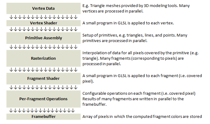
Parallelism in OpenGL with respect to the graphics pipeline can be accomplished using vertical parallelism and horizontal parallelism methods.
Vertical parallelism
Vertical parallelism is achieved by assigning the different stages of the pipeline to different processors. Strictly speaking this type of parallelism is more of functional parallelism than data parallelism.
Horizontal parallelism
Horizontal parallelism resembles data parallelism. It calls for multiple pipelines working on different sets of data. The figure illustrates the graphics pipeline parallelism. Vertical parallelism is denoted by the various stages which are executed in parallel. Horizontal parallelism is denoted by the arrows, denoting that multiple pipelines are executed in parallel.
OpenCL
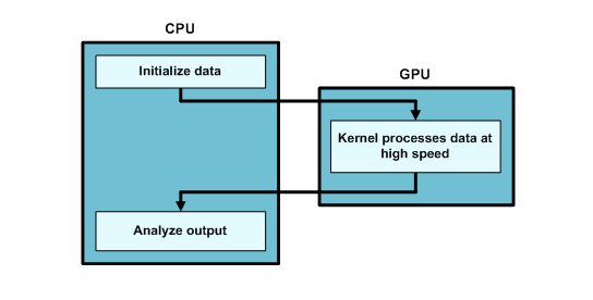
OpenCL (Open Compute Language) is only a few years old and isn't nearly as well-known as OpenGL. However, it allows developers to access GPUs (and many other devices) for purposes other than graphics. Because of this general-purpose GPU (GPGPU) processing, OpenCL is frequently employed to crunch numbers at high speed, and common OpenCL applications include data sorting, statistical computation, and frequency analysis. An OpenCL application consists of a host application that runs on the CPU and general-purpose routines called kernels that can execute on any OpenCL-compliant device, including a GPU. Figure 1.4 shows how an OpenCL application combines CPU and GPU processing.
Data parallelism in OpenCL
The following partial code is used to illustrate data parallelism in OpenCL. Here we multiply two arrays and store the result in the 3rd array. The directive __kernel before the multiplication function denotes that this function (kernel) will be executed by “N” number of PE’s, N being an argument to the function. Kernels are executed across a global domain of work-items. A program can contain multiple work-items. The kernel will get the id of the processing element in the GPU which will perform the multiplication using get_global_id(0) .
__kernel void dp_mul (__global const float *a, __global const float *b, __global float *c, int N)

{
int id = get_global_id (0);
if (id < N)
c[id] = a[id] * b[id];
}

//In main()
{   ...
// create a compute context with GPU device
context = clCreateContextFromType(NULL, CL_DEVICE_TYPE_GPU, NULL, NULL, NULL);

// create a command queue
clGetDeviceIDs( NULL, CL_DEVICE_TYPE_DEFAULT, 1, &device_id, NULL );
cl_command_queue  queue = clCreateCommandQueue(context, device_id, 0, NULL);

// Build program object
cl_program program = clCreateProgramWithSource(context, 1, &dp_mul_kernel_src, NULL, NULL);

// Build the compute program executable
clBuildProgram(program, 0, NULL, NULL, NULL, NULL);

// create the compute kernel
cl_kernel kernel = clCreateKernel(program, “dp_mul", NULL);


// Create buffers on host and device
size_t size = 100000 * sizeof(int);
int* h_buffer = (int*)malloc(size);
cl_mem a_buffer = clCreateBuffer(context, CL_MEM_READ_WRITE, size, NULL, NULL);
cl_mem b_buffer = clCreateBuffer(context, CL_MEM_READ_WRITE, size, NULL, NULL);
cl_mem c_buffer = clCreateBuffer(context, CL_MEM_READ_WRITE, size, NULL, NULL);

// Set up kernel arguments
clSetKernelArg(kernel, 0, sizeof(cl_mem), (void*)&a_buffer);
clSetKernelArg(kernel, 1, sizeof(cl_mem), (void*)&b_buffer);
clSetKernelArg(kernel, 2, sizeof(cl_mem), (void*)&c_buffer);
clSetKernelArg(kernel, 3, sizeof(int), (void*)&N);

// Write to buffer object from host memory
clEnqueueWriteBuffer(cmd_queue, a_buffer, CL_FALSE, 0, size, h_buffer, 0, NULL, NULL);
clEnqueueWriteBuffer(cmd_queue, b_buffer, CL_FALSE, 0, size, h_buffer, 0, NULL, NULL);

// Set number of work-items in a work-group
size_t localWorkSize = 256;
int numWorkGroups = (N + localWorkSize – 1) / localWorkSize; // round up
size_t globalWorkSize = numWorkGroups * localWorkSize; // must be evenly divisible by localWorkSize

//Sequence of commands scheduled for execution on queue. This command basically invokes the kernel over the global workspace.
clEnqueueNDRangeKernel(cmd_queue, kernel, 1, NULL, &globalWorkSize, &localWorkSize, 0, NULL, NULL);

// Read from buffer object to host memory
clEnqueueReadBuffer(cmd_queue, c_buffer , CL_TRUE, 0, size, h_buffer , 0, NULL, NULL);
}
The main function contains code for performing the following steps:
- Creating a context with the GPU device: This means creating an environment within which the work-items operate.
- Creating a command queue: All the work that is to be submitted to the GPU is in the form of a command queue.
- Creating a program of the source code which is to be executed in parallel and building the program: With regards to the code, this is the dp_mul function which we want to parallelize.
- Creating a kernel of the program which will be executed simultaneously across N PE’s.
- Creating buffers for reading and writing data.
- Setting up the arguments which are to be passed to the kernel.
- Work items can be grouped together to form a work group. We need to set up the number of work groups and the number of work items per work group.
- Invoking the kernel
Further readings
More information on OpenCL can be obtained on Apple. Also refer to “Introduction to OpenCL”[4] Real world technologies [7] is a good resource for more information on OpenGL, its system architecture, GPU Architecture and how data parallelism is realized using OpenGL in AMD’s Cayman GPU Architecture. NVIDIA website provides an excellent resource on CUDA, NVIDIA’s GPU parallel platform [5].
Questions
- Q1. Suppose a GPU from AMD supporting the Cayman architecture has 24 SIMD cores and 1728 processing elements in total. How many processing elements are present in 1 core?
- Q2. Name the programming model developed by NVidia
- Q3. What is the syntax used to create N kernels in CUDA C
- Q4. In CUDA, what directive is used to denote that the code is a parallel kernel?
- Q5. Who was responsible for the initial development of OpenGL?
- Q6. What is the primary difference between OpenCL and OpenGL application operations?
- Q7. What other types of parallelism are present in GPU architecture?
- Q8. What advantages do GPUs have over CPUs?
- Q9. In OpenGL, which tasks are assigned to CPUs and which tasks are handled by GPUs?
- Q10. What are the main functions of kernels in OpenCL?