CSC/ECE 506 Spring 2012/12b sb
On-chip interconnects
Introduction
Background
On-chip interconnects are a natural extension of the high integration levels that nowadays are reached with multiprocessor integration. Moore's law predicted that the number of transistors in an integrated circuit doubles every two years. This assumption has driven the integration of on-chip components and continues to show the way in the semiconductor industry.

In recent years, the main players in the chip industry keep racing to provide more cores integrated in a chip, with the multi-core (more than one core) and many-core (multi-core with so many cores that the historical multi-core techniques are not efficient any longer) technologies. This integration is known as CMP (chip multiprocessor) and lately Intel has coined the term Intel® Many Integrated Core (Intel® MIC).
To make feasible the communication in between these many cores inside of a single chip, the traditional off-chip network has proved to have limited applications. According to [5], the off-chip designs suffered from I/O bottlenecks which are a diminished problem for on-chip technologies as the internal wiring provides much higher bandwidth and overcomes the delay associated with the external traffic. Nevertheless, the on-chip designs still have some challenges that need further study. Among some of these issues are power consumption and space constraints.
Terminology
Some common terms:
- SoCs (Systems-on-a-chip), which commonly refer to chips that are made for a specific application or domain area.
- MPSoCs (Multiprocessor systems-on-chip), referring to a SoC that uses multi-core technology.
It is interesting to note that for the particular theme of this article, there are at least three different acronyms referring to the same term. These are new technologies and different researchers have adopted different nomenclature. The acronyms are:
- NoC (network-on-chip)
- OCIN (on-chip interconnection network)
- OCN (on-chip network)
Topologies
Topology refers to the layout or arrangement of interconnections among the processing elements. In general, a good topology aims to minimize network latency and maximize throughput. There are certain metrics that help with the classification and comparison of the different topology types. Some of them are defined in Solihin's [7] textbook in chapter 12.
- Degree is defined as the number of nodes that are neighbors to, or in other words, can be reached from it in one hop
- Hop count is the number of nodes through which a message needs to go through to get to the destination
- Diameter is the maximum hop count
- Path diversity is useful for the routing algorithm and is given by the amount of shortest paths that a topology offers between two nodes.
- Bisection width is the smallest number of wires you have to cut to separate the network into two halves
Topologies can be classified as direct and indirect topologies.
In a direct topology, each node is connected to other nodes, which are named neighbouring nodes. Each node contains a network interface acting as a router in order to transfer information.
In an indirect topology, there are nodes that are no computational but act as switches to transfer the traffic among the rest of the nodes, including other switches. It is called indirect because packets are switched through specific elements that are not part of the computational nodes themselves.
An example of direct topologies is 2-D Mesh. An example of indirect topology is Flattened Butterfly.
2-D Mesh

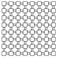
This has been a very popular topology due to its simple design and low layout and router complexity. It is often described as a k-ary n-cube , where k is the number of nodes on each dimension, and n is the number of dimensions. For example, a 4-ary 2-cube is a 4x4 2D mesh.
Another advantage is that this topology is similar to the physical die layout, making it more suitable to implement in tiled architectures. For reference, the combination of the switch and a processor is named tile.
But not everything are advantages in this topology. One of the drawbacks of 2D Meshes is that the degree of the nodes along the edges is lower than the degree of the central nodes. This makes the 2D Mesh asymmetrical along the edges, therefore from the networking perspective, there is less demand for edge channels than for central channels.
Jerger and Peh [5], provide the following information on parameters for a mesh as defined as a k-ary n-cube:
- the switch degree for a 2D mesh would be 4, as its network requires two channels in each dimension or 2n, although some ports on the edge will be unused.
- average minimum hop count:
nk/3 k even n(k/3-1/3k) k odd
- the channel load across the bisection of a mesh under uniform random traffic with an even k is k/4
- meshes provide diversity of paths for routing messages
Concentration Mesh

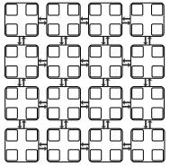
This is an evolution of the mesh topology. There is no real need to have a 1:1 relationship between the number of cores and the number of switches/routers. The Concentration mesh reduces the ratio to 1:4, i.e. each router serves four computing nodes.
The advantage over the simple mesh is the decrease in the average hop count. This is important in terms of scaling the solution. But it is not as scalable as it could seem, as its degree is confined to the crossbar complexity [1]
The reduction in the ratio introduces a lower bisection channel count, but it can be avoided by introducing express channels, as demonstrated in [8].
Another drawback is that the port bandwidth can become a bottleneck in periods of high traffic.
Flattened Butterfly

A butterfly topology is often described as a k-ary n-fly, which implies kn network nodes with n stages of kn−1 k × k intermediate routing nodes. The degree of each intermediate router is 2k.
The flattened butterfly is made by flattening (i.e. combining) the routers in each row of a butterfly topology while preserving the inter-router connections. It does non-minimal routing for load balancing improvement in the network.
Some advantages are that the maximum distance between nodes is two hops and it has lower latency and better throughput than that of the mesh topology.
For the disadvantages, it has high channel count (k2/2 per row/column), low channel utilization, and increased control complexity.
Multidrop Express Channels (MECS)

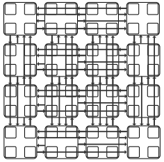
Multidrop Express Channels was proposed in [1] by Grot and Keckler. Their motivation was that performance and scalability should be obtained by managing wiring.
Multidrop Express Channels is defined by its authors as a "one to-many communication fabric that enables a high degree of connectivity in a bandwidth-efficient manner." Based on point-to-point unidirectional links. This makes for a high degree of connectivity with fewer bisection channels and higher bandwidth for each channel.
Some of the parameters calculated for MECS are:
- Bisection channel count per each row/column is equal to k.
- Network diameter (maximum hop count) is two.
- The number of nodes accessible through each channel ranges from 1 to k − 1.
- A node has 1 output port per direction
- The input port count is 2(k − 1)
The low channel count and the high degree of connectivity provided by each channel increase per channel bandwidth and wire utilization. At the same time, the design minimizes the serialization delay. It presents low network latencies due to its low diameter.
Comparison of topologies
This data is taken from the analysis done in [1].

The information in this table compares three of the topologies described above for two combinations of k which is the network radix (nodes/dimension) and c (concentration factor, 1 being no concentration).
Maximum hop count is 2 for flattened butterfly and MECS, whereas is directly proportional to k in the case of Concentrated Mesh, what makes flattened butterfly and MECS better solutions with less network latency.
The bisection channels is 1 for CMesh in both cases, but it gets doubled and even quadrupled between MECS and flattened butterfly.
The bandwidth per channel in this example is better for CMesh and MECS, getting attenuated in the case of flattened butterfly.
Examples of topologies in current NoCs
Intel
The Intel Teraflops Research Chip is made of an 8x10 mesh, and two 38-bit unidirectional links per channel. It has a bisection bandwidth of 380 GB/s, this includes data and sideband communication.
The Single-Chip Cloud Computer contains a 24-router mesh network with 256 GB/s bisection bandwidth.
Tilera
The Tilera TileGx, TilePro, and Tile64 use the Tilera’s iMesh™ on-chip network. The iMesh™ consists of five 8x8 independent mesh networks with two 32-bit unidirectional links per channel. It provides a bisection bandwidth of 320GB/s.
ST Microelectronics
IBM
Routing
The routing used on a network also has an important effect on the speed at which a packet reaches its destination. Routing can be implemented as source routing or distributed routing.
References
[1] B. Grot and S. W. Keckler. Scalable on-chip interconnect topologies. 2nd Workshop on Chip Multiprocessor Memory Systems and Interconnects, 2008.
[2] Mirza-Aghatabar, M.; Koohi, S.; Hessabi, S.; Pedram, M.; , "An Empirical Investigation of Mesh and Torus NoC Topologies Under Different Routing Algorithms and Traffic Models," Digital System Design Architectures, Methods and Tools, 2007. DSD 2007. 10th Euromicro Conference on , vol., no., pp.19-26, 29-31 Aug. 2007
[3] Ying Ping Zhang; Taikyeong Jeong; Fei Chen; Haiping Wu; Nitzsche, R.; Gao, G.R.; , "A study of the on-chip interconnection network for the IBM Cyclops64 multi-core architecture," Parallel and Distributed Processing Symposium, 2006. IPDPS 2006. 20th International , vol., no., pp. 10 pp., 25-29 April 2006
[4] David Wentzlaff, Patrick Griffin, Henry Hoffmann, Liewei Bao, Bruce Edwards, Carl Ramey, Matthew Mattina, Chyi-Chang Miao, John F. Brown III, and Anant Agarwal. 2007. On-Chip Interconnection Architecture of the Tile Processor. IEEE Micro 27, 5 (September 2007), 15-31.
[5] Natalie Enright Jerger and Li-Shiuan Peh. On-Chip Networks. Synthesis Lectures on Computer Architecture. 2009, 141 pages. Morgan and Claypool Publishers.
[6] D. N. Jayasimha, B. Zafar, Y. Hoskote. On-chip interconnection networks: why they are different and how to compare them. Technical Report, Intel Corp, 2006
[7] Yan Solihin. (2008). Fundamentals of parallel computer architecture. Solihin Pub.
[8] James Balfour and William J. Dally. 2006. Design tradeoffs for tiled CMP on-chip networks. In Proceedings of the 20th annual international conference on Supercomputing (ICS '06). ACM, New York, NY, USA, 187-198.
[9] John Kim, James Balfour, and William Dally. Flattened butterfly topology for on-chip networks. In Proceedings of the 40th International Symposium on Microarchitecture, pages 172–182, December 2007.
[10] Dubois, F.; Cano, J.; Coppola, M.; Flich, J.; Petrot, F.; , Spidergon STNoC design flow, Networks on Chip (NoCS), 2011 Fifth IEEE/ACM International Symposium on , vol., no., pp.267-268, 1-4 May 2011