Expertiza Wiki:Community Portal
Interconnection Network Architecture
Interconnection networks: What? Where? Why?
Interconnection network is a programmable system that transports data between terminals. All the terminals are connected to the interconnection network. When one terminal wishes to send data to another terminal, terminal one sends a message containing the data into the network and network delivers message to another terminal. The network is programmable because it makes different connections at different points in time. The network is system because it is composed of many components:
- Buffers
- Channels
- Switches
- Controls
These components work together to deliver data.
Interconnection networks are used in most of the digital systems that are large enough to have two components to connect. The most common examples are the computer systems and communication switches. In computer systems, they connect processors to memories and I/O devices to I/O controllers. In 1980s, most of the applications were served by a very simple interconnection networks, example, the multi-drop bus. However, this has changed. All high performance interconnections are performed by point to point interconnection networks rather then buses, and more systems that have historically been bus-based switch to networks every year. This is because of non-uniform performance scaling. The demand for interconnection performance is increasing with processor performance and network bandwidth. Buses are not able to keep up with the bandwidth demand, and point-to-point interconnection networks which both operate faster than buses and offer concurrency.
Interconnection networks are limiting factors in many systems. The interconnection network between processor and memory largely determines the memory latency and memory bandwidth. The performance of the interconnection network in a communication switch largely determines the capacity of the switch. Because the demand for interconnection has grown more rapidly that the capability of the underlying wires, interconnection has become a critical bottleneck in most systems.
History of Interconnection Networks
Networks developed along following main three parallel threads:
- Telephone switching networks
- Inter-processor communication
- Processor-memory interconnect
Early telephone networks built form the electro-mechanical crossbars or electro-mechanical step-by-step switches. As late as the 1980s, most local telephone switches were still built from electro-mechanical relays, although toll switches were completely electronic and digital by that time. Key developments in telephone switching was non-blocking, multistage Clos networks in 1953 and the Benes network in 1962. Many large telephone switches today are still built from Clos or Clos-like networks.
The first inter-processor interconnection networks were connections between the registers of neighboring processors connected in 2-D arrays. Example: Solomon machine developed in 1962. These early networks performed no routing. Therefore, processor has to explicitly relay communications to non-neighbors, making for poor performance and considerable programming complexity. By mid-1980s, router chips were developed to forward messages through intermediate nodes without processor interconnection. For example: Torus routing chip.
Inter-processor interconnection networks have gone through a series of topology fads over the years – largely motivated by packaging and other technology constraints. The early machines, like Solomon, Illian and MPP were based on simple 2-D mesh or torus networks because of their physical regularity. Starting in the late 1970s, binary n-cube or hypercube networks become popular because of their low diameter. For example, cosmic cube, the nCUBE networks. In the mid-1980s it was shown that under realistic packaging constraints low dimensional networks outperformed hypercubes and most machines returned to 2-D and 3-D mesh or torus networks. Consequently most networks built over the last decade have returned to these networks, including the J machine. For example, Cray T3D, T3E, intel DELTA. Today, the high pin bandwidth of router chips relative to message length motivates the use of networks with much higher node degree, such as butterfly and Clos network.
Processor memory interconnection networks emerge in the late 1960s when parallel processor systems incorporated alignment networks to allow any processor to access any memory bank without burdening the other processors. The smallest machines employed crossbar switches for this purpose, whereas larger machines used networks with a butterfly topology, in a dance-hall arrangement. Variations on this theme were used through the 1980s for many shared memory parallel processors.
The three interconnections network evolution recently merged. Since the 1990s, there has been little difference in the design of processor-memory and inter-processor interconnection networks. In fact, the same router chips have been used for both. A variant of Clos and Benes networks of telephony has also emerged in multiprocessor networks in the form of the fat free topology.
Interconnection Network Topology
In a multi-processor system, processors need to communicate with each other and access each other's resources. In order to route data and messages between processors, an interconnection architecture is needed.
Typically, in a multiprocessor system, message passed between processors are frequent and short1. Therefore, the interconnection network architecture must handle messages quickly by having low latency, and must handle several messages at a time and have high bandwidth.
In a network, a processor along with its cache and memory is considered a node. The physical wires that connect between them is called a link. The device that routes messages between nodes is called a router. The shape of the network, such as the number of links and routers, is called the network topology. Topology is the pattern in which the individual switches of the network are connected to other switches and to processors and memories (nodes). Direct topologies connect each switch directly to a node, while in indirect topologies at least some of the switches connect only to other switches. Direct networks are 2D mesh of the 1970s-era Illiac IV' is similar to the 1990sera 2D mesh of the Intel Paragon and the toroidal 3D mesh of the CrayT3D' and T3E.
The indirect cube network, often referred to as a multistage interconnection nemork or MIN,617 has been used in a variety of machines. This topology was used in the Staran SIMD machine of the 1970s, in which data would traverse the network from one side to the other. Allowing data to reverse direction at any stage in a bidirectional MIN (or BMIN) leads to a variation sometimes called afat-tree. MINs and their fat-tree variants are used in MIMD machines of the 1990s such as the Meiko CS-2,9 the IBM SP2," and the Thinking Machines CM. Direct networks often excel at routing local traffic patterns such as the passing of boundary data in grids Indirect networks (such as k-node MINs) can provide a variety of global communication paths by passing though the multiple stages of switches.
Types of Network Topologies
In a multi-processor system, processors need to communicate with each other and access each other's resources. In order to route data and messages between processors, an interconnection architecture is needed.
Typically, in a multiprocessor system, message passed between processors are frequent and short1. Therefore, the interconnection network architecture must handle messages quickly by having low latency, and must handle several messages at a time and have high bandwidth.
In a network, a processor along with its cache and memory is considered a node. The physical wires that connect between them is called a link. The device that routes messages between nodes is called a router. The shape of the network, such as the number of links and routers, is called the network topology.
Linear Array

The nodes are connected linearly as in an array. This type of topology is simple, however, it does not scale well. The longest distance between two nodes, or the diameter, is equivalent to the number of nodes.
Ring
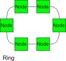
Similar structure as the linear array, except, the ending nodes connect to each other, establishing a circular structure. The longest distance between two nodes is cut in half.
2-D Mesh
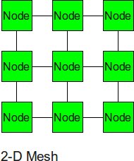
The 2-D mesh can be thought of as several linear arrays put together to form a 2-dimensional structure. Nodes that are not on the edge have 4 input or output links, or a degree of 4.
2-D Torus
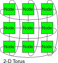
The 2-D torus takes the structure of the 2-D mesh and connects the nodes on the edges. This decreases the diameter, but the number of links is higher.
Cube
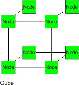
The cube can be thought of as a three-dimensional mesh.
Hypercube
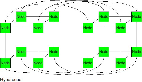
The hypercube is essentially multiple cubes put together.
Tree
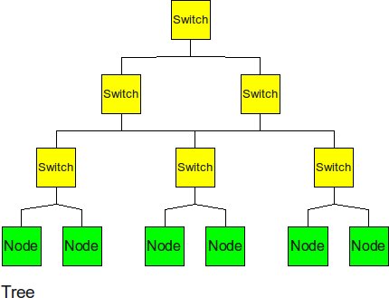
The tree is a hierarchical structure nodes on the bottom and switching nodes at the upper levels. The tree experiences high traffic at the upper levels.
Fat Tree
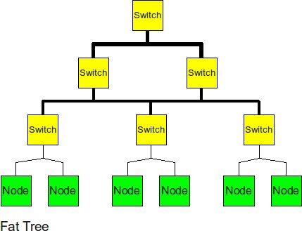
The fat tree alleviates the traffic at upper levels by "fattening" up the links at the upper levels.
Butterfly
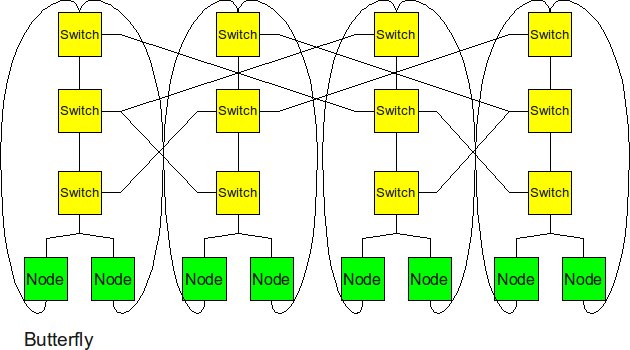
The butterfly structure is similar to the tree structure, but it replicates the switching node structure of the tree topology and connects them together so that there are equal links and routers at all levels.
Real-World Implementation of Network Topologies
In a research study by Andy Hospodor and Ethan Miller, several network topologies were investigated in a high-performance, high-traffic network2. Several topologies were investigated including the fat tree, butterfly, mesh, torii, and hypercube structures. Advantages and disadvantages including cost, performance, and reliability were discussed.
In this experiment, a petabyte-scale network with over 100 GB/s total aggregate bandwidth was investigated. The network consisted of 4096 disks with large servers with routers and switches in between2.
The overall structure of the network is shown below. Note that this structure is very susceptible to failure and congestion.
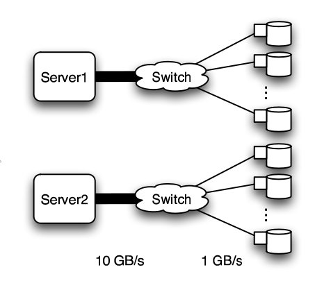
Basic structure of Hospodor and Miller's experimental network2
Fat Tree
In large scale, high performance applications, fat tree can be a choice. However, in order to "fatten" up the links, redundant connections must be used. Instead of using one link between switching nodes, several must be used. The problem with this is that with more input and output links, one would need routers with more input and output ports. Router with excess of 100 ports are difficult to build and expensive, so multiple routers would have to be stacked together. Still, the routers would be expensive and would require several of them2.
The Japan Agency for Marine-Earth Science and Technology supercomputing system uses the fat tree topology. The system connects 1280 processors using NEC processors7.
Butterfly
In high performance applications, the butterfly structure is a good choice. The butterfly topology uses fewer links than other topologies, however, each link carries traffic from the entire layer. Fault tolerance is poor. There exists only a single path between pairs of nodes. Should the link break, data cannot be re-routed, and communication is broken2.
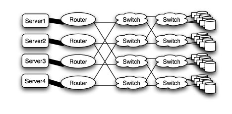
Butterfly structure2
Meshes and Tori
The mesh and torus structure used in this application would require a large number of links and total aggregate of several thousands of ports. However, since there are so many links, the mesh and torus structures provide alternates paths in case of failures2.
Some examples of current use of torus structure include the QPACE SFB TR Cluster in Germany using the PowerXCell 8i processors. The systems uses 3-D torus topology with 4608 processors7.

Mesh structure2
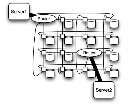
Torus structure2
Hypercube
Similar to the torii structures, the hypercube requires larger number of links. However, the bandwidth scales better than mesh and torii structures.
The CRAY T3E, CRAY XT3, and SGI Origin 2000 use k-ary n-cubed topologies.
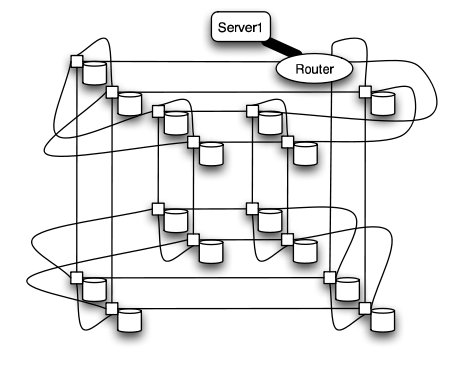
Hypercube structure2
Comparison of Network Topologies
The following table shows the total number of ports required for each network topology.
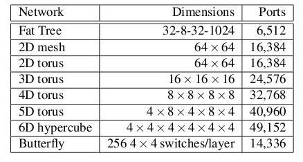
Number of ports for each topology2
As the figure above shows, the 6-D hypercube requires the largest number of ports, due to its relatively complex six-dimensional structure. In contrast, the fat tree requires the least number of ports, even though links have been "fattened" up by using redundant links. The butterfly network requires more than twice the number of ports as the fat tree, since it essentially replicates the switching layer of the fat tree. The number of ports for the mesh and torii structures increase as the dimensionality increases.
Below the average path length, or average number of hops, and the average link load (GB/s) is shown.
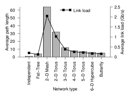
Average path length and link load for each topology2
Looking at the trends, when average path length is high, the average link load is also high. In other words, average path length and average link load are proportionally related. It is obvious from the graph that 2-D mesh has, by far, the worst performance. In a large network such as this, the average path length is just too high, and the average link load suffers. For this type of high-performance network, the 2-D mesh does not scale well. Likewise the 2-D torus cuts the average path length and average link load in half by connected the edge nodes together, however, the performance compared to other types is relatively poor. The butterfly and fat-tree have the least average path length and average link load.
The figure below shows the cost of the network topologies.
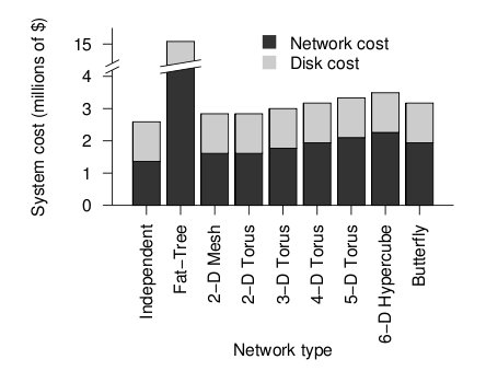
Cost of each topology2
Despite using the fewest number of ports, the fat tree topology has the highest cost, by far. Although it uses the fewest ports, the ports are high bandwidth ports of 10 GB/s. Over 2400, ports of 10 GB/s are required have enough bandwidth at the upper levels of the tree. This pushes the cost up dramatically, and from a cost standpoint is impractical. While the total cost of fat tree is about 15 million dollars, the rest of the network topologies are clustered below 4 million dollars. When the dimensionalality of the mesh and torii structures increase, the cost increases. The butterfly network costs between the 2-D mesh/torii and the 6-D hypercube.
When the cost and average link load is factored the following graph is produced.
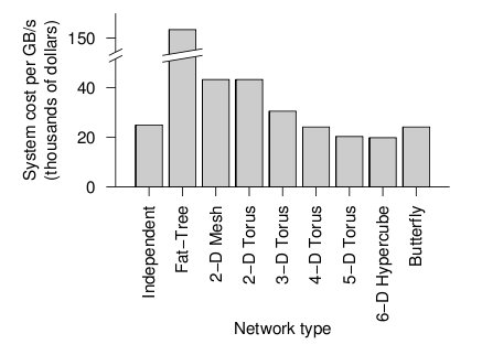
Overall cost of each topology2
From the figure above, the 6-D hypercube demonstrates the most cost effective choice on this particular network setup. Although the 6-D hypercube costs more because it needs more links and ports, it provides higher bandwidth, which can offset the higher cost. The high dimensional torii also perform well, but cannot provide as much bandwidth as the 6-D hypercube. For systems that do not need as much bandwidth, the high-dimensional torii is also a good choice. The butterfly topology is also an alternative, but has lower fault tolerance.
Routing
The routing algorithm determines what path a packet of data will take from source to destination. Routing can be deterministic, where the path is the same given a source and destination, or adaptive, where the path can change. The routing algorithm can also be partially adaptive where packets have multiple choices, but does not allow all packets to use the shortest path3.
Deadlock
When packets are in deadlock when they cannot continue to move through the nodes. The illustration below demonstrates this event.
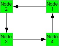
Example of deadlock
Assume that all of the buffers are full at each node. Packet from Node 1 cannot continue to Node 2. The packet from Node 2 cannot continue to Node 3, and so on. Since packet cannot move, it is deadlocked.
The deadlock occurs from cyclic pattern of routing. To avoid deadlock, avoid circular routing pattern.
To avoid circular patterns of routing, some routing patterns are disallowed. These are called turn restrictions, where some turns are not allowed in order to avoid making a circular routing pattern. Some of these turn restrictions are mentioned below.
Dimensional ordered (X-Y) routing
Turns from the y-dimension to the x-dimension are not allowed.
West First
Turns to the west are not allowed.
North Last
Turns after a north direction are not allowed.
Negative First
Turns in the negative direction (-x or -y) are not allowed, except on the first turn.
Odd-Even Turn Model
Unfortunately, the above turn-restriction models reduce the degree of adaptiveness and are partially adaptive. The models cause some packets to take different routes, and not necessarily the minimal paths. This may cause unfairness but reduces the ability of the system to reduce congestion. Overall performance could suffer3.
Ge-Ming Chiu introduces the Odd-Even turn model as an adaptive turn restriction, deadlock-free model that has better performance than the previously mentioned models3. The model is designed primarily for 2-D meshes.
Turns from the east to north direction from any node on an even column are not allowed.
Turns from the north to west direction from any node on an odd column are not allowed.
Turns from the east to south direction from any node on an even column are not allowed.
Turns from the south to west direction from any node on an odd column are not allowed.
The illustration below shows allowed routing for different source and destination nodes. Depending on which column the packet is in, only certain directions are allowed.
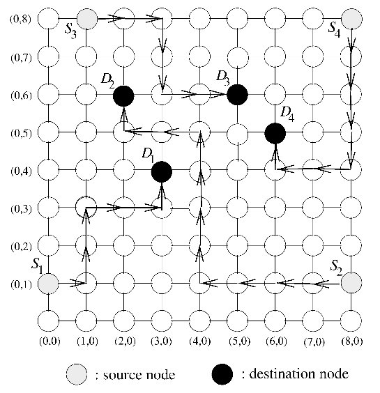
Odd-Even turn restriction model proposed by Ge-Ming Chiu3
Comparison of Turn Restriction Models
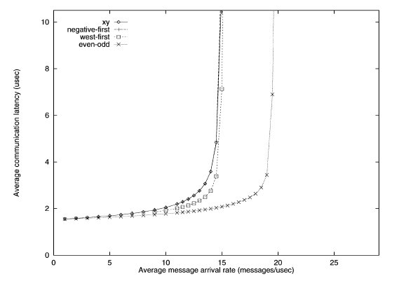
To simulate the performance of various turn restriction models, Chiu simulated a 15 x 15 mesh under various traffic patterns. All channels have bandwidth of 20 flits/usec and has a buffer size of one flit. The dimension-ordered x-y routing, west-first, and negative-first models were compared against the odd-even model.
Traffic patterns including uniform, transpose, and hot spot were conducted. Uniform simulates one node send messages to any other node with equal probability. Transpose simulates two opposite nodes sending messages to their respective halves of the mesh. Hot spot simulates a few "hot spot" nodes that receive high traffic.
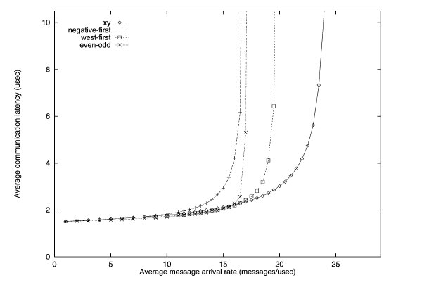
Uniform traffic simulation of various turn restriction models3
The performance of the different routing algorithms is shown above for the uniform traffic. For uniform traffic, the dimensional ordered x-y model outperforms the rest of the models. As the number of messages increase, the x-y model has the "slowest" increase in average communication latency.
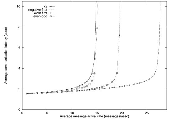
First transpose traffic simulation of various turn restriction models3
The performance of the different routing algorithms is shown above for the first transpose traffic. The negative-first model has the best performance, while the odd-even model performs better than the west-first and x-y models.
Second transpose traffic simulation of various turn restriction models3
With the second transpose simulation, the odd-even model outperforms the rest.
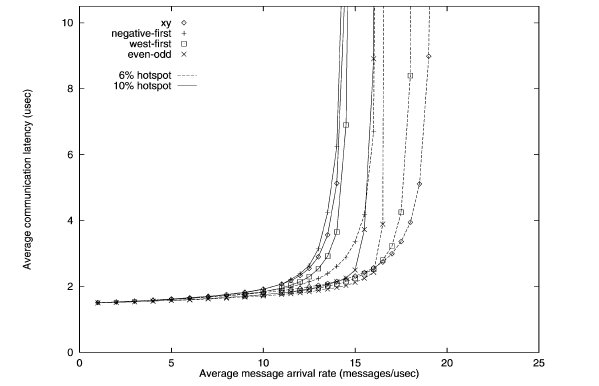
Hotspot traffic simulation of various turn restriction models3
The performance of the different routing algorithms is shown above for the hotspot traffic. Only one hotspot was simulated for this test. The performance of the odd-even model outperforms other models when hotspot traffic is 10%.
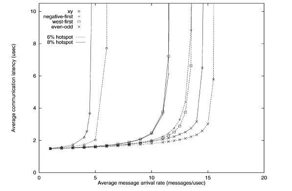
Second hotspot traffic simulation of various turn restriction models3
When the number of hotspots is increased to five, the performance of the odd-even begins to shine. The latency is lowest for both 6 and 8 percent hotspot. Meanwhile, the performance of x-y model is horrendous.
While the x-y model performs well in uniform traffic, it lacks adaptiveness. When traffic becomes hotspot, the x-y model suffers from the inability to adapt and re-route traffic to avoid the congestion caused by hotspots. The odd-even model has superior adaptiveness under high congestion.
Router Architecture
The router is a device that routes incoming data to its destination. It does this by having several input ports and several output ports. Data incoming from one of the inputs ports is routed to one of the output ports. Which output port is chosen depends on the destination of the data, and the routing algorithms.
The internal architecture of a router consists of input and output ports and a crossbar switch. The crossbar switch connects the selects which output should be selected, acting essentially as a multiplexer.
Router technology has improved significantly over the years. This has allowed networks with high dimensionality to become feasible. As shown in the real-world example above, high dimensional torii and hypercube are excellent choice of topology for high-performance networks. The cost of high-performance, high-radix routers has contributed to the viability of these types of high dimensionality networks. As the graph below shows, the bandwidth of routers has improved tremendously over a period of 10 years4.
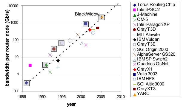
Bandwidth of various routers over 10 year period4
Looking at the physical architecture and layout of router, it is evident that the circuitry has been dramatically more dense and complex.
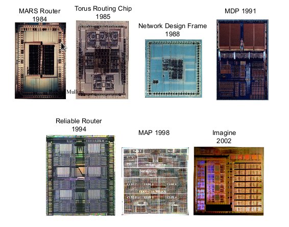
Router hardware over period of time4
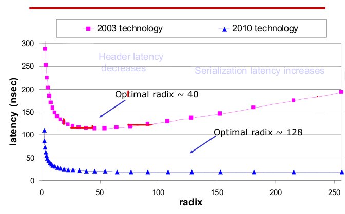
Radix and latency of routers over 10 year period4
The radix, or the number of ports of routers has also increased. The current technology not only has high radix, but also low latency compared to last generation. As radix increases, the latency remains steady.
With high-performance routers, complex topologies are possible. As the router technology improves, more complex, high-dimensionality topologies are possible.
Fault Tolerant Routing
Fault-tolerant routing means the successful routing of messages between any pair of non faulty nodes in the presence of faulty components6. With increased number of processors in a multiprocessor system and high data rates reliable transmission of data in event of network fault is of great concern and hence fault tolerant routing algorithms are important.
Fault Models
Faults in a network can be categorized in two types:
1.Transient Faults5 : A transient fault is a temporary fault that occurs for a very short duration of time. This fault can be caused due to change in output of flip-flop leading to generation of invalid header. These faults can be minimized using error controlled coding. These errors are generally evaluated in terms of Bit Error Rate.
2.Permanent Faults5: A permanent fault is a fault that does not go away and causes a permanent damage to the network. This fault could be due to damaged wires and associated circuitry. These faults are generally evaluated in terms of Mean Time between Failures.
Fault Tolerance Mechanisms (for permanent faults)
The permanent faults can be handled using one of the two mechanisms:
1.Static Mechanism: In static fault tolerance model, once the fault is detected all the processes running in the system are stopped and the routing tables are emptied. Based on the information of faults the routing tables are re-calculated to provide a fault free path.
2.Dynamic Mechanisms: In dynamic fault tolerance model, it is made sure that the operation of the processes in the network is not completely stalled and only the affected regions are provided cure. Some of the methods to do this are:
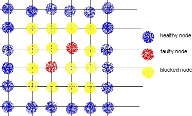
a.Block Faults: In this method many of the healthy nodes in vicinity of the faulty nodes are marked as faulty nodes so that no routes are created close to the actual faulty nodes. The shape of the region could be convex or non-convex, and is made sure that none of the new routes introduce cyclic dependency in the cyclic dependency graph (CDG).
DISADVANTAGE: This method causes lot of healthy nodes to be declared as faulty leading to reduction in system capacity.
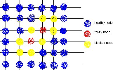
b.Fault Rings: This method was introduced by Chalasani and Boppana. A fault tolerant ring is a set of nodes and links that are adjunct to faulty nodes/links. This approach reduces the number of healthy nodes to be marked as faulty and blocking them.
References
1 Solihin text
2 Interconnection Architectures for Petabyte-Scale High-Performance Storage Systems
3 The Odd-Even Turn Model for Adaptive Routing
4 Interconnection Topologies:(Historical Trends and Comparisons)
5 Efficient mechanisms to provide fault tolerance in interconnection networks for PC clusters, José Miguel Montañana Aliaga.
6 Adaptive Fault Tolerant Routing Algorithm for Tree-Hypercube Multicomputer, Qatawneh Mohammad
7 TOP500 Supercomputing Sites