User:Mdcotter: Difference between revisions
| Line 197: | Line 197: | ||
===Proposed Reliable Omega Design=== | ===Proposed Reliable Omega Design=== | ||
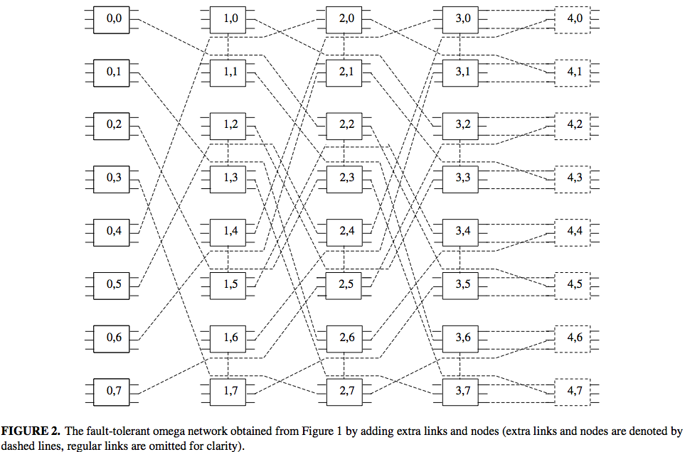
To create a more reliable design, it must ensure that the system maintains its structure after a fault | |||
[[File:Figure_2_Proposed_Omega.png|550px|center]] | [[File:Figure_2_Proposed_Omega.png|550px|center]] | ||
Revision as of 23:42, 16 April 2012
New Interconnection Topologies
Introduction
Parallel processing has assumed a crucial role in the field of supercomputing. It has overcome the various technological barriers and achieved high levels of performance. The most efficient way to achieve parallelism is to employ multicomputer system. The success of the multicomputer system completely relies on the underlying interconnection network which provides a communication medium among the various processors. It also determines the overall performance of the system in terms of speed of execution and efficiency. The suitability of a network is judged in terms of cost, bandwidth, reliability, routing ,broadcasting, throughput and ease of implementation. Among the recent developments of various multicomputing networks, the Hypercube (HC) has enjoyed the highest popularity due to many of its attractive properties. These properties include regularity, symmetry, small diameter, strong connectivity, recursive construction, partitionability and relatively small link complexity.
Metrics Interconnection Networks
Network Connectivity
Network nodes and communication links sometimes fail and must be removed from service for repair. When components do fail the network should continue to function with reduced capacity. Network connectivity measures the resiliency of a network and its ability to continue operation despite disabled components i.e. connectivity is the minimum number of nodes or links that must fail to partition the network into two or more disjoint networks The larger the connectivity for a network the better the network is able to cope with failures.
Network Diameter
The diameter of a network is the maximum internode distance i.e. it is the maximum number of links that must be traversed to send a message to any node along a shortest path. The lower the diameter of a network the shorter the time to send a message from one node to the node farthest away from it.
Narrowness
This is a measure of congestion in a network and is calculated as follows: Partition the network into two groups of processors A and B where the number of processors in each group is Na and Nb and assume Nb < = Na. Now count the number of interconnections between A and B call this I. Find the maximum value of Nb / I for all partitionings of the network. This is the narrowness of the network. The idea is that if the narrowness is high ( Nb > I) then if the group B processors want to send messages to group A congestion in the network will be high ( since there are fewer links than processors )
Network Expansion Increments
A network should be expandable i.e. it should be possible to create larger and more powerful multicomputer systems by simply adding more nodes to the network. For reasons of cost it is better to have the option of small increments since this allows you to upgrade your network to the size you require ( i.e. flexibility ) within a particular budget. E.g. an 8 node linear array can be expanded in increments of 1 node but a 3 dimensional hypercube can be expanded only by adding another 3D hypercube. (i.e. 8 nodes)
Hypercube
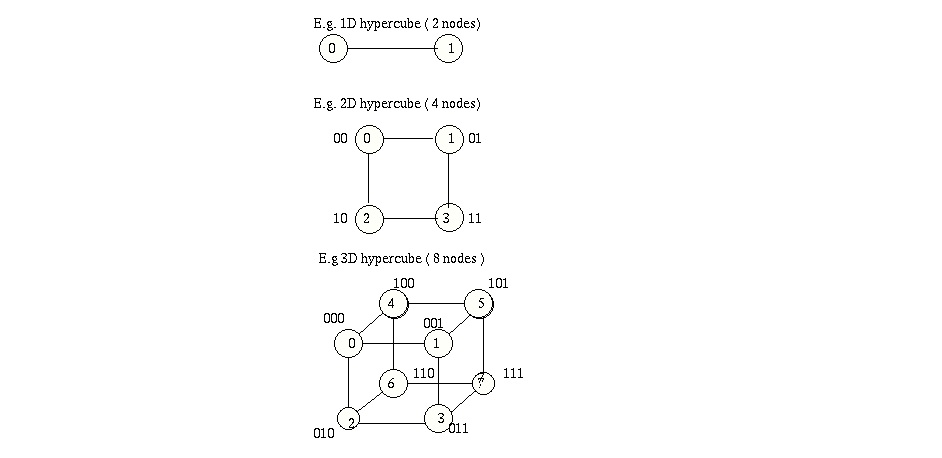
Hypercube networks consist of N = 2n nodes arranged in a k dimensional hypercube. The nodes are numbered 0 , 1, ....2n -1 and two nodes are connected if their binary labels differ by exactly one bit. The attractiveness of the hypercube topology is its small diameter, which is the maximum number of links (or hops) a message has to travel to reach its final destination between any two nodes. For a hypercube network the diameter is identical to the degree of a node n = log2N. There are 2n nodes contained in the hypercube; each is uniquely represented by a binary sequence bn-1bn-2...b0 of length n. Two nodes in the hypercube are adjacent if and only if they differ at exactly one bit position. This property greatly facilitates the routing of messages through the network.
In addition, the regular and symmetric nature of the network provides fault tolerance. Most Important parameters of an interconnection network of a multicomputer system are its scalability and modularity. Scalable networks have the property that the size of the system (e.g., the number of nodes) can be increased with minor or no change in the existing configuration. Also, the increase in system size is expected to result in an increase in performance to the extent of the increase in size. a major drawback of the hypercube network is its lack of scalability, which limits its use in building large size systems out of small size systems with little changes in the configuration. As the dimension of the hypercube is increased by one, one more link needs to be added to every node in the network. Therefore, it becomes more difficult to design and fabricate the nodes of the hypercube because of the large fan-out.
Twisted Cubes
Twisted cubes are variants of hypercubes. The n-dimensional twisted cube has 2n nodes and n2n-1 edges. It possesses some desirable features for interconnection networks . Its diameter, wide diameter, and faulty diameter are about half of those of the n-dimensional hypercube. A complete binary tree can be embedded into it. The five-dimensional twisted cube TQ5, where the end nodes of a missing edge are marked with arrows labeled with the same letter is shown below
Extended Hypercube
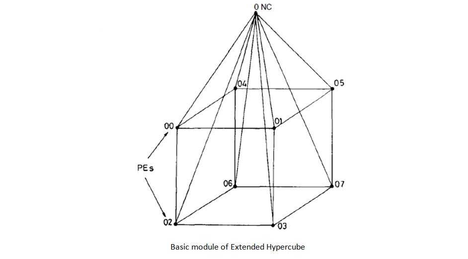
The hypercube networks are not truly expandable because we have to change the hardware configuration of all the nodes whenever the number of nodes grows exponentially, as the nodes have to be provided with additional ports. an incompletely populated hypercube lacks some of the properties which make the hypercube attractive in the first place. Complicated routing algorithms are necessary for the incomplete hypercube. Extended Hypercube(EH) retains the attractive features of the hypercube topology to a large extent. The EH is built using basic modules consisting of a k-cube of processor elements (PE’s) and a Network Controller (NC) as shown in the figure below. The NC is used as a communication processor to handle intermodule communication; 2k such basic modules can be interconnected via 2k NC’s, forming a k-cube among the NC’s. The EH is essentially a truly expansive, recursive structure with a constant predefined building block. The number of I/O ports for each PE (and NC) is fixed and is independent of the size of the network. The EH structure is found to be most suited for implementing a class of highly parallel algorithms. The EH can emulate the binary hypercube in implementing a large class of algorithms with insignificant degradation in performance. The utilization factor of the EH is higher than that of the Hypercube.
Balanced Hypercube
As the number of processors in a system increases, the probability of system failure can be expected to be quite high unless specific measures are taken to tolerate faults within the system. Therefore, a major goal in the design of such a system is fault tolerance. These systems are made fault-tolerant by providing redundant or spare processors and/or links. When an active processor (where tasks are running) fails, its tasks are dynamically transferred to spare components. The objective is to provide an efficient reconfiguration by keeping the recovery time small. It is highly desirable that the reconfiguration process is a decentralized and local one, so fault status exchange and task migration can be reduced or eliminated. The Balanced Hypercube is a variation of the Hypercube structure that can support consistently recoverable embedding. Balanced hypercubes belong to a special type of load balanced graphs [10] that can support consistently recoverable embedding. In a load balanced graph G = (V, E), with V as the node set and E as the edge set, for each node v there exists another node v’, such that v and v’ have the same adjacent nodes. Such a pair of nodes v and v’ is called a matching pair.
In a load balanced graph, a task can be scheduled to both v and v’ in such a way that one copy is active and the other one is passive. If node v fails, we can simply shift tasks of v to v’ by activating copies of these tasks in v’. All the other tasks running on other nodes do not need to be reassigned to keep the adjacency property, i.e., two tasks that are adjacent are still adjacent after a system reconfiguration. Note that the rule of v and v’ as primary and backup are relative. We can have an active task running on node v with its backup on node v’, while having another active task running on node v’ with its backup on node v. With a sufficient number of tasks and a suitable load balancing approach, we can have a balanced use of processors in the system.
A graph G is load balanced if and only if for every node in G there exists another node matching it, i.e., these two nodes have the same adjacent nodes. Hence they are called a matching pair. A completely connected graph with an even number of nodes is load balanced, while several other commonly used graph structures, such as meshes, trees, and hypercubes, are not. In the figures shown labeled as BHn, n is called the dimension of the balanced hypercube.
Balanced Varietal Hypercube
A n dimensional, balanced varietal hypercube consists of 2^2n nodes. Every node connects 2n nodes, which are of 2 types :a)Inner nodes b)Outer nodes through hyperlinks.
a) Inner node: Case I: When a0 is even:
(i) <(a0+1)mod 4, a1,a2..... an-1> (ii)< (a0-2)mod 4, a1,a2..... an-1>
Case II: When a0 is odd:
(i) <(a0-1)mod 4, a1,a2..... an-1> (ii)< (a0+2)mod 4 ,a1,a2..... an-1>
b) Outer node: Case I: When a0=0,3:
(i) For ‘ai’ = 0
<(a0+1) mod 4 , a1,....,(ai+1)mod 4 a2,....,an-1> <(a0-1) mod 4 , a1,....,(ai+1)mod 4 a2,....,an-1>
(ii) For ‘ai’ = 3
<(a0+1) mod 4 , a1,....,(ai-1)mod 4 ,....,an-1> <(a0-1) mod 4 , a1,....,(ai-1)mod 4 ,....,an-1>
Case II: when a0=1,2 and ai= 0,3:
<(a0+1) mod 4 , a1,....,(ai+2)mod 4 ,....,an-1> <(a0-1) mod 4 , a1,....,(ai+2)mod 4 ,....,an-1>
Case III: when a0=0,1
(i) For ai=1
<(a0+1) mod 4 , a1,....,(ai+2)mod 4 ,....,an-1> <(a0-1) mod 4 , a1,....,(ai-1)mod 4 ,....,an-1> (ii) For ai=2 <(a0+1) mod 4 , a1,....,(ai+2)mod 4 ,....,an-1> <(a0+1) mod 4 , a1,....,(ai+2)mod 4 ,....,an-1>
Case IV: when a0=2,3
(i) For ai=1 <(a0+1) mod 4 , a1,....,(ai-1)mod 4 ,....,an-1> <(a0-1) mod 4 , a1,....,(ai+2)mod 4 ,....,an-1>
(ii) For ai=2
<(a0+1) mod 4 , a1,....,(ai+1)mod 4 ,....,an-1> <(a0-1) mod 4 , a1,....,(ai+2)mod 4,....,an-1>
Properties of a Balanced Varietal Hypercube
The degree of any node in the Balanced varietal hypercube of dimension n is equal to 2n.
An n-dimensional Balanced varietal hypercube has n* 22n edges.
The diameter of an n-dimensional Balanced varietal hypercube is
 i. 2n for n=1
 ii. ceil(n+n/2) for n> 1.
The average distance conveys the actual performance of the network better in practice. The summation of distance of all nodes from a given node over the total number of nodes determines the average distance of the network. In the Balanced varietal hypercube the average distance is given by 1/(2^2n)∑[d(0,0,0),k]
Cost is an important factor as far as an interconnection network is concerned. The topology which possesses minimum cost is treated as the best candidate. Cost factor of a network is the product of degree and diameter. The cost of an n-dimensional balanced varietal hypercube is given by 2n* ceiling(n + n/2).
Routing in Balanced Varietal Hypercube
In routing process, each processor along the path considers itself as the source and forwards the message to a neighbouring node one step closer to the destination. The algorithm consists of a left to right scan of source and destination address. Let r be the right most differing bit (quarternary) position. The numbers to the right of ur is not to be considered as they lie on the same BVHr . Since the diameter of BVH1 is 2 there is atleast one vertex which is a common neighbour of ur and vr. If d is an element such that d neighbour of ur is also a neighbour of vr.Then d is choosen such that ur=vr. Then in the next step d1 is choosen such that ur-1=vr-1. This process continues until u=v.
Algorithm:Procedure Route(u,v)
{
r: right most differing bit position
d:choice such that dur=vr
route to d-neighbour else
route to r-neighbour (k and v are adjacent)
if (u and v are not adjacent) then
d1=choice that dur-1=dvr-1
route to d1 neighbour
}
Broadcast in Balanced Varietal Hypercube
Broadcasting refers to a method of transferring a message to all recipients simultaneously.The broadcast primitive finds wide application in the control of distributed systems and in parallel computing. An optimal one-to-all broadcast algorithm is presented for BVHn assuming that concurrent communication through all ports of each processor is possible. It consists of (n+1) steps as shown below.
Procedure Broadcast(u,n):
Step1: send message to 2n neighbours of u
Step 2: one of 2n nodes sends message to its 2n-1 neighbours. Then n nodes from the rest nodes
send message to their (2n-2) neighbours.
Step 3: continue step 2 till all the nodes get the message.
Step 4: end
Reliable Omega interconnected networks
Introduction
The omega network topology supports both one-to-one routing and broadcast routing. Since every node in the system is a fixed size, the system can be easily scaled to larger systems. The omega network belongs to the multistage interconnection networks (MINs). Since the omega network is designed for larger systems, it depends heavily on reliability, therefore we will also discuss an enhanced version of the omega network <ref name="omega">Bataineh, Sameer; Qanzu'a, Ghassan.; , "Reliable Omega Interconnected Network for Large-Scale Multiprocessor Systems" The Compter Journal, 2003. vol. 46, no. 5, pp.467-475, 203 [1]</ref>.
The original omega distributed-memory multiprocessor is of
- N=L x (log2(L) + 1)
- N = number of switches
- L = number of levels
- (log2(L) + 1) = number of stages

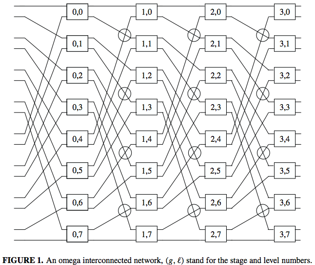
Figure 1 above has 32 nodes with 8 levels. Each node as four links connected it to the previous and next stages. The connections go as follows.
- Output link x on stage g connects to input link σn(x) on stage g+1
- 0 ≤ g < log2(L)
- x is an n+1 bit number if the form x = {bn,bn-1,...,b1,b0}
- σn(x) = {bn−1,...,b2,b1,b0,bn}
- In the Figure 1 above L=8, N=32, n=3, and x=0-15 and has a four bit representation
Proposed Reliable Omega Design
To create a more reliable design, it must ensure that the system maintains its structure after a fault

Node Replacement Policy and Reconfiguration
Reliability Analysis
K-Ary n-cube Interconnection networks
Quiz
Referecences
<references />


