ECE506 CSC/ECE 506 Spring 2012/2b az: Difference between revisions
m (Made clarifixations of gl_Position in the shader program) |
m (Added reference to inspiration for GLSL code) |
||
| Line 1: | Line 1: | ||
= Data Parallel Programming with AMD 69xx Series Graphics Processing Unit = | = Data Parallel Programming with AMD 69xx Series Graphics Processing Unit = | ||
| Line 205: | Line 204: | ||
</pre> | </pre> | ||
This shader program was developed by the author after having referenced the GLSL manual <ref name=GLSLReference/>. | |||
The vertex coordinates v are passed in as an ‘attribute’, which is an indexed element of the (bound and enabled) vertex array or vertex buffer object. The model-view-projection matrix A is loaded by the host program into device memory as a ‘uniform’, instructing the vertex program compiler that it should be treated as a constant across all vertices. The current vertex v is transformed by model-view-projection matrix A and stored into the gl_Position variable. gl_Position is a unique variable to vertex shaders, and is a standard output that must be written otherwise it is undefined, but could be initialized to (0,0,0,0) depending on the OpenGL driver implementation<ref name ="HD6900Manual"/><ref name=OpenGL42/>. More details on the expected output variables of shaders, consult the GLSL shading manual <ref name=GLSLReference/>. | The vertex coordinates v are passed in as an ‘attribute’, which is an indexed element of the (bound and enabled) vertex array or vertex buffer object. The model-view-projection matrix A is loaded by the host program into device memory as a ‘uniform’, instructing the vertex program compiler that it should be treated as a constant across all vertices. The current vertex v is transformed by model-view-projection matrix A and stored into the gl_Position variable. gl_Position is a unique variable to vertex shaders, and is a standard output that must be written otherwise it is undefined, but could be initialized to (0,0,0,0) depending on the OpenGL driver implementation<ref name ="HD6900Manual"/><ref name=OpenGL42/>. More details on the expected output variables of shaders, consult the GLSL shading manual <ref name=GLSLReference/>. | ||
Revision as of 03:03, 7 February 2012
Data Parallel Programming with AMD 69xx Series Graphics Processing Unit
Graphics processing units (GPUs) are parallel architectures designed to perform fast computations for graphics applications, such as rasterizing, per pixel lighting calculations, and tessellation. Since their introduction, significant effort has been made in enabling general purpose computations such as fluid simulations, rigid and soft-body physics simulations, and particle simulations.
Reasons that GPUs are being tapped for general purpose computations include performance, cost, scalability, and ubiquity.
Modern GPU architectures are SIMD vector processors that can realize speedup in the linear algebra calculations involved in graphics and general purpose scientific and engineering applications.
This article presents an introduction to data-parallel programming on GPUs through exploration of the programming model, the architecture and instruction set of the AMD HD 6900 series GPUs, and finally an example involving vertex translation, rotation, and perspective projection transformations.
The example is designed to explore different facets of the architecture, and include discussion of the AMD HD 6900 instruction set and OpenGL ES 2.0<ref name=OpenGLES2>A. Munshi, J. Leech. OpenGL ES Common Profile Specification. The Khronos Group, Revision 2.0.25 (version 2.0), November 2, 2010. URL http://www.khronos.org/registry/gles/specs/2.0/es_full_spec_2.0.25.pdf</ref> vertex and fragment shader programs. OpenGL ES 2.0 is a subset of the desktop OpenGL 4.2<ref name=OpenGL42>M. Segal, K. Akeley, C. Frazier, J. Leech, P. Brown. The OpenGL Graphics System: A Specification. The Khronos Group, Version 4.2, January 19, 2012. URL http://www.opengl.org/registry/doc/glspec42.core.20120119.pdf</ref>, thus the example can be applied to mobile and desktop GPUs.
Architectural Overview
The AMD HD 6900 series, AKA Cayman, a member of the Northern Islands-family of graphics processors, is a parallel architecture designed to interface with it’s own local device memory, the host system memory, and a host application. A block diagram of the processor architecture and data exchanges with the device and host are shown in Fig. 1.
The processor consists of a memory controller for interfacing with device memory and the host memory, a command processor which parses commands placed in system memory by the host and shared by the GPU, an array of data-parallel processors (DDP) configured as compute pipelines with their own local shared memory, a combined shared memory for all pipelines, an L1 input cache for the entire DPP array, an L2 input cache, an output cache, a dispatch processor to issue commands to specific pipelines and DPPs, a set of program counters for the DPP array, and an instruction and constant cache. <ref name="HD6900Manual">Advanced Micro Devices, Inc.. Reference Guide: HD 6900 Series Instruction Set Architecture. Advanced Micro Devices, Inc., One AMD Place, P.O. Box 3453, Sunnyvale, CA 94088-3453, Revision 1.1, November 2011. URL http://developer.amd.com/sdks/amdappsdk/assets/AMD_HD_6900_Series_Instruction_Set_Architecture.pdf</ref>
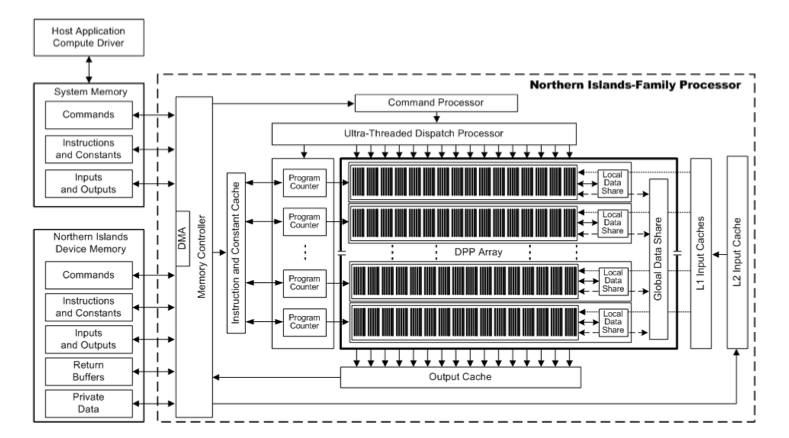
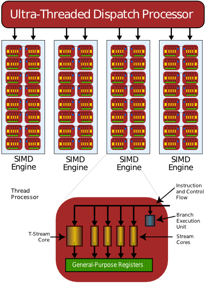
Each compute pipeline is a SIMD engine with it’s own local data, called a local data share (LDS). Each SIMD engine is made up of a number of thread processors (Streaming Processor Units, or SPUs). Each SPU contains 4 stream cores, one branch execution unit, and general purpose registers (GPRs). Each of these stream cores are simple ALUs, chosen as such to be able to operate on r,g,b,a values for pixels, or x,y,z,w coordinates for vectors. Due to the 4 stream cores in each thread processor, the SIMD instructions are known as VLIW4, or very large instruction word with 4 elements. <ref name=AMDATIGPULecture>Antti P. Miettinen. AMD/ATI GPU hardware. February 15, 2010. URL https://wiki.aalto.fi/display/GPGPUK2010/AMD+GPU</ref>
Interestingly, the AMD HD 6800 series SPU (shown in Fig. 2) contained 5 stream cores, where the fifth was a transcendental core (sine, cosine, etc.) that enabled common per vertex calculations, such as 4 component dot products and a transcendental scalar for lighting, simultaneously. The t-core was introduced by AMD for DirectX9 to allow vertex shaders to improve performance when executing lighting calculations with the per vertex operations. As DX9 became scarce and DX10 and DX11 became more ubiquitous (through Windows Vista and Windows 7), AMD found that the number of stream cores being utilized on average was 3.4, indicating that in many cases the t-core was not being utilized. This, combined with the increase in general purpose GPU computing without the need for the t-core, led to the decision to drop the t-core, convert to a VLIW4 instruction set, and allowed for more SPUs to be included on the same size die. This positions AMD to increase utilization in their hardware in games and general purpose computing applications. <ref name="HD6970AnandTech">Ryan Smith. AMD's Radeon HD 6970 & Radeon HD 6950: Paving The Future For AMD. AnandTech, December 15, 2010. URL http://www.anandtech.com/show/4061/amds-radeon-hd-6970-radeon-hd-6950/4</ref>
Instruction and data flow - hardware perspective
A basic overview is given describing the flow of instructions and data to the GPU and to the processing elements, then from the processing elements to the greater GPU to the display, and if necessary, back to the host. The host places commands into the memory-mapped GPU registers in the system memory. These commands can include requesting the GPU to copy data from the system memory to device memory by message passing.
The command processors reads these instructions and data through the memory controller from system memory. Once the command is complete, a hardware generated interrupt is sent to the host from the command processor<ref name ="HD6900Manual"/>.
The device memory is updated with instruction and data from system memory through the memory controller via message passing from the host.
The dispatch processor requests a pipeline compute unit to execute an instruction thread (a kernel) by passing it the location of the kernel in device memory, an identifying pair, and a conditional value<ref name ="HD6900Manual"/>. The dispatch processor also attempts to balance the load of the compute units by leveling loading the threads. <ref name="R600TechReport">Scott Wasson. AMD Radeon HD 2900 XT graphics processor: R600 revealed. Tech Report, May 14, 2007. URL http://www.techreport.com/reviews/2007q2/radeon-hd-2900xt/index.x?pg=1</ref>
The pipeline compute unit loads the instructions and data from the instruction and data cache (originally from device memory), and executes the kernel from beginning to end. Data and results can be input from and written to device memory through the memory controller and data caches. It can also “load data from off-chip memory into on-chip general-purpose registers (GPRs) and caches”<ref name ="HD6900Manual"/>. Computation and writes to memory can be executed conditionally, allowing for parallel algorithms to be used on conditions per data element. Additionally, each compute unit contains its own sequencer to optimize it’s performance by rearranging instructions where possible<ref name="R600TechReport"/>.
Programming Model
Both task and data-parallel programming models are applicable to modern GPUs, but this article focuses on the data-parallel model.
The intended usage of the architecture is to provide batch instructions to the GPU through kernels (implemented as shader programs in OpenGL or compute programs in OpenCL) or load/store/execute/state configuration instructions (through OpenGL or OpenCL API commands) that are placed into memory on the host which is shared with the GPU through memory mapping. Additionally, host programs and kernel programs can be written for general purpose computing applications in language extensions such as NVIDIA’s CUDA <ref name=CUDA>NVIDIA Corporation. CUDA: Parallel Programming and Computing Platform. NVIDIA Corporation, Santa Clara, CA. 2012. URL http://www.nvidia.com/object/cuda_home_new.html</ref>, OpenGL and the shader language GLSL <ref name=GLSLReference>J. Kessenich, D. Baldwin, R. Rost. The OpenGL Shading Language, Language Version 4.20. The Khronos Group, Revision 8, September 2, 2011. URL http://www.opengl.org/registry/doc/GLSLangSpec.4.20.8.clean.pdf</ref>, and OpenCL <ref name=OpenCLReference>The Khronos OpenCL Working Group. The OpenCL Specification, Version 1.2. The Khronos Group, Revision 15, November 15, 2011. URL http://www.khronos.org/registry/cl/specs/opencl-1.2.pdf</ref>.
The GPU then uses message passing from the driver application to localize the kernels and command instructions into device memory and cache for execution. The data upon which these kernels operate is also provided to the GPU through message passing via load/store commands in the shared memory space, and localized in the device memory.
The instructions and data on board the processor are streamed through instruction and data caches, and outputs written to output caches. The output caches normally place data back into device memory from which rasterization can be performed (in the case of vertex shaders, geometry shaders, or hull shaders), or, further in the rendering pipeline, back into framebuffers in the device memory for display (in the case of pixel shaders) after being placed into video RAM (VRAM). General purpose compute applications would output into device memory (to avoid PCIe bus transfer overhead for multi-stage calculations) or system memory directly.
Data-parallel programming with OpenGL
OpenGL is an industry standard graphics API, with support built into drivers for almost all graphics hardware (GPUs) and some CPUs directly. Newer versions of OpenGL support a programmable graphics pipeline designed to exploit the parallel architectures available in modern GPUs. This discussion is limited to the new programmable pipeline available in OpenGL 4.2, of which OpenGL ES 2.0 (supported by iOS, Android, Playstation 3, etc.) is a subset.
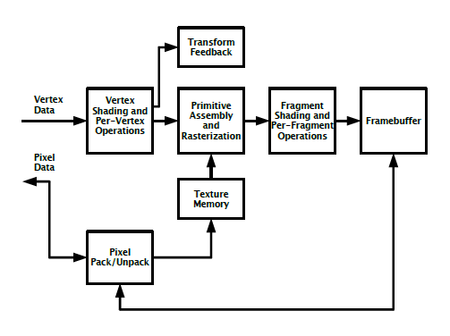
The programmable pipeline allows data to be placed into the graphics device memory, and instructs the GPU (through shader programs) to operate on the data in memory to perform the geometric transforms (translation, rotation, perspective projection, etc.), lighting transforms (vertex lighting, per pixel lighting, etc.) and any other desired calculations on data in device memory before it is placed into VRAM for display or put back in system memory. The flexibility of the programmable pipeline is powerful, making it a backbone of the support for other general purpose compute APIs, such as OpenCL. Fig. 3 illustrates the programmable pipeline.
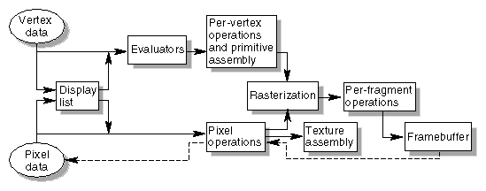
The programmable pipeline is in contrast with the fixed-function pipelines of the past in which the graphics processor always performed the same steps in order, and data had to be passed to the OpenGL state machine in the correct sequence. The output was the framebuffer, which was then put into VRAM for displaying. Any general purpose calculations were difficult to contrive into the pipeline, and framebuffer to system memory copy time was very slow, so it was not effective. Fig. 4 illustrates a fixed function pipeline.
In the programmable pipeline, data parallel programming is done by creating vertex and fragment (previously called pixel) shader programs. A vertex shader program is executed on all vertex elements in an array containing vertex data, and can thus be executed as kernels in parallel across multiple SIMD engines, where each SPU operates on an individual vertex (size 1, 2, 3, or 4 floating point elements). Similarly, each fragment shader is executed on all pixels in an array containing pixel data (possibly interleaved with vertex data), and are also executed as kernels in parallel across multiple SIMD engines, where each SPU operates on an individual pixel (1, 2, 3, or 4 floating point elements). The packing, interleaving, and aligning of data is left to the programmer, but must be considered carefully to reduce cache misses and ensure optimal performance on fetches. As mentioned before, conditional computations can be performed in shaders.
For general purpose compute applications, fragment shaders and vertex shaders can be used on any arbitrary data arrays that are placed in device memory.
In general, algorithms for data-parallel processing contain inner and outer loops. The inner loops, which operate on atomic elements in the data sets and perform the calculations to be vectorized, occur in the kernels, are processed by the GPU, and executed in the DPP array compute units. The outer loops, which traverse the data sets to identify the elements, occur in the host programs. OpenGL distinguishes the host and device as server and client.
OpenGL’s programmable pipeline abstracts the traversal of data from the programmer, leaving the programmer to load the data to the client and implement the inner loops through shader programs while the outer loops are performed automatically.
Shaders for modern GPUs in OpenGL programs are written using GLSL syntax, which is a C like language that is then compiled into instructions for the vendor specific GPU instruction set by means of a shader compiler that is built into the GPU drivers. This process, and a fictional example of a shader having been compiled, will be shown in the example.
Data is loaded into device memory through the use of vertex buffer objects or vertex array objects.
Vertex buffers are arrays that store vertex data, such as coordinates, texture coordinates, normal vectors (for lighting), and possibly interleaved vertex color information. The application programmer provides OpenGL with a pointer to the array in device memory, assigns it a unique id, and then requests OpenGL to enable the array for that unique id. Finally, OpenGL is instructed to draw the vertex data, and is given info on how to treat the vertices (as triangle strips, as points, etc.). This method is not preferred, however, since the programmer effectively controls where the data is stored in system memory and indirectly requests when to copy data from system to device memory through the draw function. The alternative method is to request that OpenGL generate a buffer in device memory, assign it a unique id itself, and have the programmer pass the vertex data into it once. Then, as it is requested to be drawn, the data is bound from device memory and drawn without the overhead of the system to device transfer<ref name="iOSOpenGLESGuide">Apple Inc. OpenGL ES programming guide for iOS. Apple Inc. February 24, 2011. URL https://developer.apple.com/library/ios/#documentation/3DDrawing/Conceptual/OpenGLES_ProgrammingGuide/Introduction/Introduction.html</ref>.
The preferred alternative to vertex buffer objects is vertex array objects. Almost identical, the difference between the two is that the state changes requested of OpenGL (number of elements per vertex in the vertex buffer, the stride for vertices in the array, etc.) that are executed prior to each draw call with vertex buffer objects are stored within the array in vertex array objects. Thus, drawing a vertex array doesn’t require that the device incur the performance penalty of reconfiguring the pipeline each time<ref name="iOSOpenGLESGuide"/>
Data-parallel programming with OpenCL
OpenCL is an API that adds an extension to the C99 language that provides a generic programming interface to general purpose parallel computing on heterogeneous processor architectures, including GPUs. OpenCL allows for data-parallel and task-parallel programming models.
OpenCL is an attempt at abstracting general purpose parallel programming, but underneath it resorts to sending commands through OpenGL graphics drivers and their shader compilers if available, rather than implementing their own microcode generators for each GPU available. This abstraction allows the application programmer to avoid putting his task in the framework of a graphics pipeline with vertices or pixels.
Example - Translation, Rotation, and Perspective Projection Transformation of Vertices
This example covers the transformation of vertices in a scene using OpenGL with GLSL, and will be used to illustrate: passing arrays of data to the device memory, passing a kernels of per-element (per vertex) instructions to the device memory, parallel execution of a kernel on a data array (vertices)
In a 3d scene, vertices exist as (x,y,z,w) elements in relation to a coordinate system. In graphics, the method used to position the camera, from which the scene is rendered, is to create a “model view” matrix and transform all the vertices in the scene. Next, the vertices are generally transformed by a perspective projection transformation matrix in order to add perspective into the scene.
The modelview matrix encodes the translation and rotation of the vertices in the scene relative to the position and view direction of the camera. For this example, the modelview matrix will be assumed to be the identity matrix, implying that the camera is facing the default direction in OpenGL coordinate space (towards the negative z direction), with it’s “up” vector pointing to positive y, and it is expecting to be able to view vertices that exist in front of it with at least negative z coordinates.
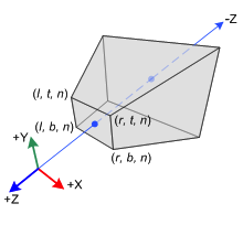
The perspective projection transformation matrix defines the volume, known as a frustum, that determines the field of view, the “near” plane (closest point to the camera which will be rendered), the “far” plane (furthest point which will be rendered), and the aspect ratio of the frustum (ratio of width to height). Figures 5 and 6 show the frustum with the coordinate system and the perspective projection matrix. For the purposes of this example, the perspective projection matrix will be assumed to be calculated separately.
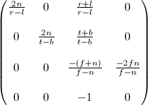
The transformation for each vertex is a matrix multiplication between the perspective projection matrix A and the vertex v (for N vertices), with the result stored in vertex p (for N vertices). The modelview matrix is not included in the calculation because it is assumed to be the identity matrix. The calculation is shown below:

Pseudocode
Pseudo code to perform this calculation on the (0 <= n <= N-1) vertex is shown below.
a:= fetch(projectionMatrix);
for i:= 0 to 3 do
  p[n][i]:= 0;
  for j:= 0 to 3 do
    p[n][i]:= p[n][i] + a[i][j] * v[n][j];
  end;
end;
Since the GPU is a vector processor with each SIMD engine containing multiple SPUs that can handle 4 element dot products on two vectors on multiple vector simultaneously, the pseudocode can be rewritten to closely resemble a vertex shader program on the (0 <= n <= N-1) vertex:
a:= LDS_fetch(projectionMatrix); // fetch from LDS of local SIMD engine
p[n][i]:= 0, (0 <= i <= 3);
p[n][i]:= p[n][i] + a[i][j] * v[n][j],
  (0 <= i <= 3) and (0 <= j <= 3) and (0 <= n <= N-1);
The vertex program can simultaneously calculate each element of the resultant vertex simultaneously, given enough parallel SPUs exist in the unutilizied SIMD engines. Further, given enough free SPU and SIMD engines exist, all elements of each transformed vertex can be computed simultaneously (but must be stored at the correct offset in memory to form vertex data arrays).
Shader Program
Under construction, reviews 3,5, and 6 recommend more and clearer explanations of the code. Review 5 suggested citing sources used when creating the shader program
To accomplish the pseudocode above in GLSL, GLSL operations must exist that can:
- access the model-view-projection matrix from device memory
- perform vector dot products
- store results into an output buffer
The GLSL code required for this vertex shader is given below:
//
//  Shader.vsh
//
//  Created by Adnan Zafar on 1/29/12.
//

attribute vec4 v;			// vertex v[n]
uniform mat4 A;				// model-view-projection matrix A

void main()
{
    gl_Position = A * v;		// p[n] = A x v
}
This shader program was developed by the author after having referenced the GLSL manual <ref name=GLSLReference/>.
The vertex coordinates v are passed in as an ‘attribute’, which is an indexed element of the (bound and enabled) vertex array or vertex buffer object. The model-view-projection matrix A is loaded by the host program into device memory as a ‘uniform’, instructing the vertex program compiler that it should be treated as a constant across all vertices. The current vertex v is transformed by model-view-projection matrix A and stored into the gl_Position variable. gl_Position is a unique variable to vertex shaders, and is a standard output that must be written otherwise it is undefined, but could be initialized to (0,0,0,0) depending on the OpenGL driver implementation<ref name ="HD6900Manual"/><ref name=OpenGL42/>. More details on the expected output variables of shaders, consult the GLSL shading manual <ref name=GLSLReference/>.
More details on attributes and uniforms are found in the host program section.
The GPU driver compiles the shader program and produces code in the AMD HD 6900 series instruction set. To accomplish this efficiently on this architecture, instructions must exist that:
- load data from the input cache into GPRs, and
- perform a 4 element vector dot product in one instruction and store into a GPR, and
- move the result from GPRs to the output buffers.
Instruction Set
The instruction set for the AMD HD 6900 series GPU is broken into subsets for control flow and clause types. Clauses are homogeneous groups of instructions including ALU, fetch through texture cache (or memory), and global data share instructions.<ref name ="HD6900Manual"/>
Each set of instructions that are grouped into a program have limitations. For example, a control flow program can be no larger than 2^28 bytes, with a maximum of 128 slots for ALU clauses taking 256 dwords, and 16 slots for texture cache and global data share clauses taking 64 dwords. Instructions in one clause are executed serially, but if the clauses themselves have no dependencies, then groups of clauses can be executed in parallel.<ref name ="HD6900Manual"/>
Since instructions can be up to the size of double words, then they are encoded in microcode, and specific instructions utilize one or two words for the necessary parameters. A full description of the microcode formats can be found in <ref name ="HD6900Manual"/>. A set of numbers after a clause, such as CF_WORD[0,1], indicate the number of words in the microcode. For alignment purposes, these are usually powers of 2, with unused words set to 0.
The instructions relevant to this example are fetch through texture cache and ALU instructions. The optimization of clauses is outside the scope of this example, as is the efficient loading of data and the vertex shader program from system memory into device memory.
Memory Access
Assuming that the matrix A, the vertex array, and the program are in device memory, then instructions must be used to load the data into the GPRs of each SPU.
The instruction used to load vertex data from device memory into the GPRs for the SPU are done as texture cache (TC) clauses. Although it sounds non-intuitive, the TC clauses are used to read both pixel and vertex data, since the vertex cache was removed from the HD 6900 series. The TC clauses are initiated with the TC instruction and the vertex fetch is done with the FETCH microcode, repeated over each necessary fetch for the vertices and rows of the model-view-projection matrix.<ref name ="HD6900Manual"/>
An EXPORT instruction is used to push the data from the GPRs after vertex shader execution back into the position buffer for use in the remainder of the programmable pipeline. Once the last vertex clause has completed, the EXPORT_DONE instruction should be issued to signal to the hardware that the position buffer should be finalized. Alternatively, the data could be pushed to another buffer and back to device memory is being used for general purpose compute applications.<ref name ="HD6900Manual"/>
ALU Instructions
The DOT4 instruction can be utilized to perform a 4 element dot product between two vectors stored in GPRs. To accomplish this, the vertices and rows of each matrix must be loaded into GPRs. The results of the DOT4 instruction is placed as a scalar into the previous vector (PV) register in the x element, thus afterwards, it is required that the scalar be moved to a GPR prior to the end of the ALU clause.<ref name ="HD6900Manual"/>
Shader Microcode
An abbreviated example of AMD HD 6900 series microcode for reading the vertex and model-view-projection matrix data into GPRs, transforming each vertex by the model-view-projection matrix by SIMD dot products, and writing back to a position buffer is given below<ref name ="HD6900Manual"/>.
The first portion of the microcode (steps 1 through 7) is used to load the model-view-projection matrix A from the texture cache into GPRs in the SPUs. To do so, instruction 1 starts a loop over each row of matrix A, and instruction 2 issues a texture cache clause that is used to initiate a fetch instruction. As discussed earlier, clauses begin a set of following instructions, and in this case, it is just a set of fetch instructions. Within the loop, the fetch instruction in step 3 is repeated four times to load each 4 x 32 bit floating point element row vector from the texture cache into GPRs. Step 7 ends the loop which is used to load matrix A into registers in the SPUs.
Now that the matrix A has been loaded into registers (GPRs) by rows, the microcode loops through each vertex in the scene, issues a fetch to bring it into a GPR, and computes the dot product between it and each row vector of A, storing the resultant into a floating point element in a GPR to represent the perspective transformed vertex. Instruction 8 initiates the loop over the vertices, and instructions 9 and 10 initiate a texture cache clause and fetch the vertex from the texture cache and load it into a GPR. Step 11 initiates an ALU clause which is used to signal the beginning of four dot products, one dot product per row vector of A. Instructions 12 through 15 are the dot products of A with the current vertex, and the results are stored as a transformed vertex with the MOV instruction in step 16. Step 17 ceases the loop.
Next, the results must be moved out of GPRs into a position buffer which is then used in rasterization. Step 18 is used to initiate the export to move data from GPRs into the position buffer. If this is the final export prior to the end of the microcode, the export would be replaced by an EXPORT_END.
Finally, step 19 issues the instruction that flags the end of the microcode.
Details of the instruction set can be found in <ref name ="HD6900Manual"/>.
| Order | Instruction and parameter summary | Microcode format | Description |
| 1 | LOOP_START [...] | CF_WORD[0,1] | Initiate loop through all A matrix rows |
| 2 | TC [...] | CF_WORD[0,1] | Initiate a texture cache clause to read all A matrix rows into GPRs |
| 3,4,5,6
(per row) |
FETCH [VC_INST_FETCH | |
TEX_WORD[0,1,2] | Fetch A matrix row data from TC at coordinate (x,y) stored in elements x, y, z, and w of the nth GPR holding the address. Use a non-structured vertex fetch and write the data back to the LDS. Do not use a coalesced vertex fetch.
Also store the result in GPR m as four 32-bit floats into x,y,z,w. Start reading from offset 0, with no endian swap, 0 stride, no constants from another thread or a constant buffer. |
| 7 | LOOP_END [...] | CF_WORD[0,1] | End the loop over the rows. |
| 8 | LOOP_START [...] | CF_WORD[0,1] | Initiate a loop over all vertices |
| 9 | TC [...] | CF_WORD[0,1] | Execute a texture cache clause to real all vertices into GPRs |
| 10 | FETCH [...] | TEX_WORD[0,1,2] | Fetch vertex data from TC into GPR |
| 11 | ALU [...] | CF_WORD[0,1] | Initiate an ALU clause to calculate the dot product of each vertex with one row of A at a time. (This can be optimized by doing another loop to make this parallel, since the entire clause is executed serially.) |
| 12,13,14,15 | DOT4 [...] | ALU_WORD[0,1] | Calculate the dot product of row 0,1,2,3 with the vertex in GPR |
| 16 | MOV [...] | ALU_WORD[0,1] | Move the scalar result into a destination GPR |
| 17 | LOOP_END [...] | CF_WORD[0,1] | End the loop over vertices. |
| 18 | EXPORT / EXPORT_END [...] | CF_WORD[0,1] | Export from GPRs to the position buffer. |
| 19 | END | CF_WORD[0,1] | End the kernel |
Host Program
Example code for an OpenGL 2.0+ host program is given below.
The host program is used to set up the OpenGL environment, load the shader programs to the GPU device memory, copy the scene vertices and the model-vew-projeciton matrix A into device memory, and execute the shader and render the results to the screen. The example host program is written in C for OpenGL ES 2.0, but is compatible with OpenGL 4.2 since it utilizes the programmable pipeline and no fixed function elements.
The host program first references the functional library headers required for OpenGL and others to be loaded by the preprocessor. This varies from platform to platform, and is dictated by the rest of the host program's referenced functions.
Next, variables are declared to provide integers to store the attribute number for the position and to store the uniform number for the model-view-projection matrix. Attributes are a mechanism in programmable pipeline OpenGL used to pass a single element (vector) of an array in memory to a shader, one element at a time until the shader has been executed for each available element. Uniforms are data that remain constant and are passed identically and entirely to each shader program, rather than being subdivided and passed element by element to each shader program. In both cases, attributes and uniforms are registered by the host program with OpenGL with index numbers, thus these variables declare the indices for the position attribute and the model-view-projection matrix uniform. More information on uniforms and attributes can be found in <ref name=OpenGL42/>.
Next the vertex data and model-view-projection matrices are declared as floating point arrays. Typically the model-view-projection matrix is recalculated each rendering frame, and in the case of first person shooter games, is positioned at the eye location of the player character. Vertex data is not normally declared as constants either, and are usually either generated by the host program dynamically, or loaded from files containing data stored in custom or proprietary 3d data formats. More information can be found on cameras and 3d data formats in <ref name=OpenGL11RedBook/>, or in newer revisions.
The host program is charged with loading the source code for the shader programs to the vendor supplied OpenGL driver, requesting the driver to compile and link the shader, and ask if the shader build was valid. This process is executed in the build function. The shader source is loaded from a .vsh (vertex shader) file and passed to the driver and assigned a handle which is henceforth used to refer to this specific shader. The shader is compiled and linked by its shader handle. The built shader is then validated, and OpenGL is polled to determine the validation status. If the shader is valid, it is set as the current shader to be used, otherwise an exception is taken.
The config function is used to set up the attributes and uniforms used by the shader program. First, the model-view-projection matrix A is registered as a uniform with it's attribute index as a handle. Next, a pointer to the address of the vertex data is supplied to OpenGL, and is then copied from host memory to device memory through enabling the attribute array. This is an example of message passing used to copy data from the host to the GPU device memory.
The display function is used to clear and draw the vertex data. First, the color buffer (used to hold data in memory for displaying to the screen) is cleared, along with the depth buffer, which is used to contain the depth of each element rendered. This essentially clears the screen and other buffers that must be cleared from rendering frame to rendering frame. Information on these buffers can be found in <ref name=OpenGL42/> and explained conceptually in <ref name=OpenGL11RedBook/> or in newer versions. Next, OpenGL is instructed to draw the enabled arrays as a strip of triangles (vertices that define a contiguous set of triangles). Since the vertex position data were enabled as an attribute array, this array is drawn by executing the current shader program in memory on each attribute element. Lastly, now that the scene has been rendered and rasterized into memory, it must be drawn to the screen. This varies by platform, programming language, and operating system, so is excluded from the example.
Finally, the main function is used to build the shaders and configure the attributes and uniforms for the shader, and if successful, a display loop is executed until the program terminates.
This example host program was influenced by this authors work after having read the iOS OpenGL ES 2.0 programming guide<ref name="iOSOpenGLESGuide"/>, and was adapted for desktop OpenGL and the C programming language.
#include <...>

// enumerations for attributes and uniform variables into the shader
int ATTRIBUTE_POSITION = 1;
int UNIFORM_MODELVIEWPROJ = 1;

float vertex_data = {...};
float model_view_projection = {...};

// compile, link, and validate the shader program
int build()
{
  char shader_source[1024];
  GLuint shader_handle = 0;
  GLint valid_status = 0;

  if(read_file_to_string(“Shader.vsh”, &shader_program))
    return 1;

  // load the shader source into the GLSL compiler
  glShaderSource(&shader_handle, 1, &shader_source, NULL);

  // compile the GLSL shader (use error checking when debugging...)
  glCompileShader(shader_handle);

  // link the GLSL shader
  glLinkProgram(shader_handle);

  // validate the shader
  glValidateProgram(shader_handle);

  // get a validation status
  glGetProgramiv(shader_handle, GL_VALIDATE_STATUS, &valid_status);

  // return 0 if shader is good
  if(status)
    return glUseProgram(shader_handle);
  else
    return 1;
}

// set the OpenGL configuration states
int config()
{
  // set up the model view projection matrix to pass into the shader
  glUniformMatrix4fv(uniforms[UNIFORM_MODELVIEWPROJ], 1, GL_FALSE, model_view_projection);

  // configure and enable the vertex buffers for sending to shader
  glVertexAttribPointer(ATTRIBUTE_POSITION, 4, GL_FLOAT, GL_FALSE, 0, vertex_data);
  glEnableVertexAttribArray(ATTRIBUTE_POSITION);

  return 0;
}


void display()
{
  // clear the display
  glClearColor(0, 0, 0, 1);
  glClear(GL_COLOR_BUFFER_BIT | GL_DEPTH_BUFFER_BIT);

  // draw the vertices
  glDrawArrays(GL_TRIANGLE_STRIP, 0,  sizeof(vertex_data)/(4*sizeof(GLfloat)));

  … // present the framebuffer to the window
}

int main()
{
  … // set up the window and device context

  if(!build() && !config())
    while(1)
      display();

  return 1;
}
Practicality
Note that due to the relative complexity of performing this computation through microcode, GLSL and other high level shading languages were developed. Such languages, as can be seen from the GLSL provided previously, provide a simplified means to execute data-parallel programming through applications. Graphics device driver developers are still required to explore the GPU instruction sets in order to implement the shading language compilers and to fully exploit the performance of their unique hardware.
Definitions
Under construction, suggested from review 1,2,3,4,5 to include inlined links to definitions
- Word
- Definition of the word
- A longer phrase needing definition
- Phrase defined
Suggested Readings
Under construction, suggested from review 3
To learn more about OpenGL, including tutorials on how to implement different features in applications, refer to the guides on OpenGL.org. REFERENCE AND MORE DETAIL NEEDED
To learn more about ETC.
References
Complete - reviews 1,2,3,5,6,7 recommended changing the links to hypertext and being inlined in the article.
<references/>