CSC/ECE 506 Spring 2012/8a fu: Difference between revisions
| Line 307: | Line 307: | ||
SOURCE : Yan Solihin, "Fundamentals of Parallel Computer Architecture," Solihin Publishing & Consulting LLC, 2008, pp. 168-173. | SOURCE : Yan Solihin, "Fundamentals of Parallel Computer Architecture," Solihin Publishing & Consulting LLC, 2008, pp. 168-173. | ||
SOURCE states that many processors rely on software to implement the prefetch special instruction. SOURCE also mentions that effective prefecthing | SOURCE states that many processors rely on software to implement the prefetch special instruction. SOURCE also mentions that effective prefecthing is characterized by '''coverage''' (the fraction of initial cache misses prefetch has transitioned into cache hits), '''accuracy''' (the fraction of prefetches that generated cache hits), and '''timeliness''' (how early the prefetch arrives). [http://en.wikipedia.org/wiki/Prefetch_buffer Prefetch buffers] help prefetching obtain the desired characteristics. | ||
<br/> | <br/> | ||
Revision as of 02:06, 19 March 2012
Introduction to bus-based cache coherence in real machines
SMP Architecture
Most parallel software in the commercial market relies on the shared-memory programming model in which all processors access the same physical address space. And the most common multiprocessors today use SMP architecture which use a common bus as the interconnect. In the case of multicore processors ("chip multiprocessors," or CMP) the SMP architecture applies to the cores treating them as separate processors. The key problem of shared-memory multiprocessors is providing a consistent view of memory with various cache hierarchies. This is called cache coherence problem. It is critical to achieve correctness and performance-sensitive design point for supporting the shared-memory model. The cache coherence mechanisms not only govern communication in a shared-memory multiprocessor, but also typically determine how the memory system transfers data between processors, caches, and memory.
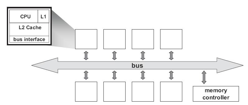
At any point in logical time, the permissions for a cache block can allow either a single writer or multiple readers. The coherence protocol ensures the invariants of the states are maintained. The different coherent states used by most of the cache coherence protocols are as shown in Table 1:
| States | Access Type | Invariant |
| Modified | read, write | all other caches in I state |
| Exclusive | read | all other caches in I state |
| Owned | read | all other caches in I or S state |
| Shared | read | no other cache in M or E state |
| Invalid | - | - |
Snooping Protocols
MSI Protocol
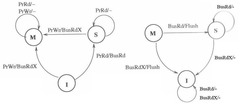
MSI is a three-state write-back invalidation protocol which is one of the earliest snooping-based cache coherence-protocols. It marks the cache line in Modified (M) ,Shared (S) and Invalid (I) state. Invalid means the cache line is either not present or is invalid state. If the cache line is clean and is shared by more than one processor , it is marked shared. If cache line is dirty and the processor has exclusive ownership of the cache line, it is present in Modified state. BusRdx causes others to invalidate (demote) to I state. If it is present in M state in another cache, it will flush. A BusRdx, even if it causes a cache hit in S state, is promoted to M (upgrade) state.
The state diagram of the MSI protocol is shown below. Note that the left part shows the response to processor-side requests, and the right part shows the response to snopper-side requests.[21]
Real Architectures using MSI
MSI protocol was first used in SGI IRIS 4D series. SGI produced a broad range of MIPS-based (Microprocessor without Interlocked Pipeline Stages) workstations and servers during the 1990s, running SGI's version of UNIX System V, now called IRIX. The 4D-MP graphics superworkstation brought 40 MIPS(million instructions per second) of computing performance to a graphics superworkstation. The unprecedented level of computing and graphics processing in an office-environment workstation was made possible by the fastest available Risc microprocessors in a single shared memory multiprocessor design driving a tightly coupled, highly parallel graphics system. Aggregate sustained data rates of over one gigabyte per second were achieved by a hierarchy of buses in a balanced system designed to avoid bottlenecks.
The multiprocessor bus used in 4D-MP graphics superworkstation is a pipelined, block transfer bus that supports the cache coherence protocol as well as providing 64 megabytes of sustained data bandwidth between the processors, the memory and I/O system, and the graphics subsystem. Because the sync bus provides for efficient synchronization between processors, the cache coherence protocol was designed to support efficient data sharing between processors. If a cache coherence protocol has to support synchronization as well as sharing, a compromise in the efficiency of the data sharing protocol may be necessary to improve the efficiency of the synchronization operations. Hence it uses the simple cache coherence protocol which is the MSI protocol.
With the simple rules of MSIprotocol enforced by hardware, efficient synchronization and efficient data sharing are achieved in a simple shared memory model of parallel processing in the 4D-MP graphics superworkstation.
Implementation Complexities
Synapse protocol
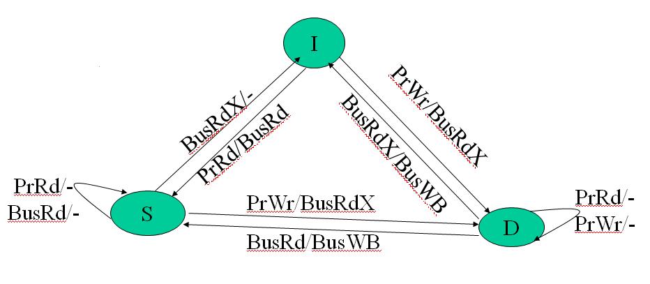
From the state transition diagram of MSI, we observe that there is transition to state S from state M when a BusRd is observed for that block. The contents of the block is flushed to the bus before going to S state. It would look more appropriate to move to I state thus giving up the block entirely in certain cases. This choice of moving to S or I reflects the designer's assertion that the original processor is more likely to continue reading the block than the new processor to write to the block. In synapse protocol, used in the early Synapse multiprocessor, made this alternate choice of going directly from M state to I state on a BusRd, assuming the migratory pattern would be more frequent. More details about this protocol can be found in these papers published in late 1980's Coherence protocols: evaluation using a multiprocessor simulation model and Synapse tightly coupled multiprocessors: a new approach to solve old problems
In Synapse protocol M state is called D (Dirty) state. The following is the state transition diagram for Synapse protocol:
Real Architectures using Synapse
Nothing can be found on an any actual architecture using the Synapse cache-coherence protocol. From the abstract of the paper written by Steve Frank and Armond Inselberg in 1984, "Synapse Tightly Coupled Multiprocessors: A New Approach to Solve Old Problems", Synapse was theoretical.
The The BABYLON Project did one example of a Synapse cache coherence protocol with atomic synchronization actions.
Implementation Complexities
In the Synapse system, memory contention is reduced by designing a processor cache employing a non-write-through algorithm to minimized bandwidth between cache and shared memory. The Synapse Expansion Bus includes an ownership level protocol between processor caches.[24]
MESI
The main drawback of MSI is that each read-write sequence incurs two bus transactions irrespective of whether the cache line is stored in only one cache or not. Highly parallel programs that have little data sharing suffer the most from this. MESI protocol solves this problem by introducing the Exclusive state to distinguish between a cache line stored in multiple caches and a line stored in a single cache. Let us briefly see how the MESI protocol works. For a more detailed version refer Solihin textbook pg. 215.
MESI coherence protocol marks each cache line in of the Modified, Exclusive, Shared, or Invalid state.
- Invalid : The cache line is either not present or is invalid
- Exclusive : The cache line is clean and is owned by this core/processor only
- Modified : This implies that the cache line is dirty and the core/processor has exclusive ownership of the cache line,exclusive of the memory also.
- Shared : The cache line is clean and is shared by more than one core/processor
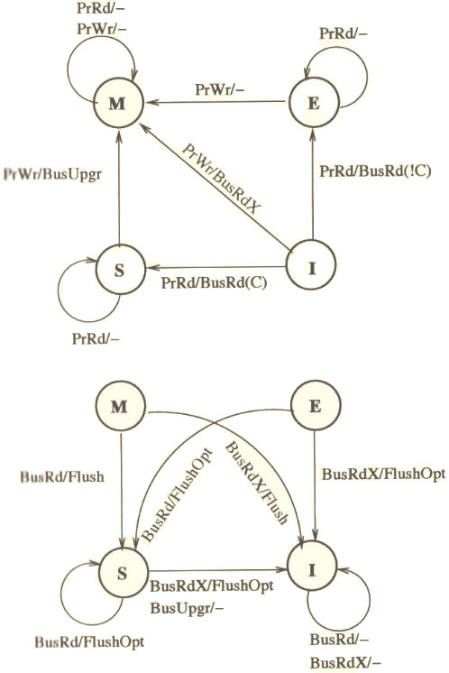
The MESI protocol works as follows: A line that is fetched, receives E, or S state depending on whether it exists in other processors in the system. A cache line gets the M state when a processor writes to it; if the line is not in E or M-state prior to writing it, the cache sends a Bus Upgrade (BusUpgr) signal or as the Intel manuals term it, “Read-For-Ownership (RFO) request” that ensures that the line exists in the cache and is in the I state in all other processors on the bus (if any). A table is shown below to summarize the MESI protocol.
| Cache Line State: | Modified | Exclusive | Shared | Invalid |
| This cache line is valid? | Yes | Yes | Yes | No |
| The memory copy is… | out of date | valid | valid | - |
| Copies exist in caches of other processors? | No | No | Maybe | Maybe |
| A write to this line | does not go to bus | does not go to bus | goes to bus and updates cache | goes directly to bus |
State transition diagram for MESI protocol is shown below.[21]
Real Architectures using MESI
Intel's Pentium Pro microprocessor, introduced in 1992, was the first Intel architecture microprocessor to support symmetric multiprocessing in various multiprocessor configurations. SMP and MESI protocol was the architecture used consistently until the introduction of the 45-nm Hi-k Core micro-architecture in Intel's (Nehalem-EP) quad-core x86-64. The 45-nm Hi-k Intel Core microarchitecture utilizes a new system of framework called the QuickPath Interconnect which uses point-to-point interconnection technology based on distributed shared memory architecture. It uses a modified version of MESI protocol called MESIF, which introduces the additional Forward state. (The state diagram of MESI transitions that occur within the Pentium's data cache can be found on page 63 of Pentium Processor System Architecture: Second Edition by Don Anderson, Tom Shanley, MindShare, Inc)
The ARM11 MPCore and Cortex-A9 MPCore processors support the MESI cache coherency protocol.[19] ARM MPCore defines the states of the MESI protocol it implements as:
| Cache Line State: | Modified | Exclusive | Shared | Invalid |
| Copies in other caches | NO | NO | YES | - |
| Clean or Dirty | DIRTY | CLEAN | CLEAN | - |
The coherency protocol is implemented and managed by the Snoop Control Unit (SCU) in the ARM MPCore, which monitors the traffic between local L1 data caches and the next level of the memory hierarchy. At boot time, each core can choose to partake in the coherency domain or not. Unless explicit system calls bound a task to a specific core (processor affinity), there are high chances that a task will at some point migrate to a different core, along with its data as it is used. Migration of tasks is not efficiently implemented in literal MESI implementation, so the ARM MPCore offers two optimizations that allow for MESI compliance and migration of tasks: Direct Data Intervention (DDI) (in which the SCU keeps a copy of all cores caches’ tag RAMs. This enables it to efficiently detect if a cache line request by a core is in another core in the coherency domain before looking for it in the next level of the memory hierarchy)and Cache-to-cache Migration (where if the SCU finds that the cache line requested by one CPU present in another core, it will either copy it (if clean) or move it (if dirty) from the other CPU directly into the requesting one, without interacting with external memory). These optimizations reduce memory traffic in and out of the L1 cache subsystem by eliminating interaction with external memories, which in effect, reduces the overall load on the interconnect and the overall power consumption.[19]
Other architectures that use the MESI cache-coherence protocol include the L2 cache of the IBM POWER4 processor[20], the L2 cache of the Intel Itanium 2 processor[21], and the Intel Xeon[22].
Implementation Complexities
One implementation complexity already mentioned is the inefficiency of task migration in MESI that the ARM MPCore addresses.[19] Another possible implementation complexity is found during the replacement of a cache line: one possible MESI implementation requires a message to be sent to main memory when a cache line is flushed (i.e. an E to I transition), as the line was exclusively in one cache before it was removed. It is possible to avoid this replacement message if the system is designed so that the flush of a modified (exclusive) line requires an acknowledgment from main memory. However, this requires the flush to be stored in a 'write-back' buffer until the reply arrives (to ensure the change is successfully propagated to memory).[23]
MESIF
Let us now walk through a briefing on the MESIF protocl:
The MESIF protocol, used in the latest Intel multi-core processors was introduced to accommodate the point-to-point links used in the QuickPath Interconnect. Using the MESI protocol in this architecture would send many redundant messages between different processors, often with unnecessarily high latency. For example, when a processor requests a cache line that is stored in multiple locations, every location might respond with the data. As the the requesting processor only needs a single copy of the data, the system would be wasting the bandwidth. As a solution to this problem, an additional state, Forward state, was added by slightly changing the role of the Shared state. Whenever there is a read request, only the cache line in the F state will respond to the request, while all the S state caches remain dormant. Hence, by designating a single cache line to respond to requests, coherency traffic is substantially reduced when multiple copies of the data exist. Also, on a read request, the F state transitions from F to S state. That is, when a cache line in the F state is copied, the F state migrates to the newer copy, while the older one drops back to S. Moving the new copy to the F state exploits both temporal and spatial locality. Because the newest copy of the cache line is always in the F state, it is very unlikely that the line in the F state will be evicted from the caches. This takes advantage of the temporal locality of the request. The second advantage is that if a particular cache line is in high demand due to spatial locality, the bandwidth used to transmit that data will be spread across several nodes. All M to S state transition and E to S state transitions will now be from M to F and E to F. The F state is different from the Owned state of the MOESI protocol as it is not a unique copy because a valid copy is stored in memory. Thus, unlike the Owned state of the MOESI protocol, in which the data in the O state is the only valid copy of the data, the data in the F state can be evicted or converted to the S state, if desired.
More information on the QuickPath Interconnect and MESIF protocol can be found at Introduction to QuickPath Interconnect
Real Architectures using MESIF
Implementation Complexities
MOESI
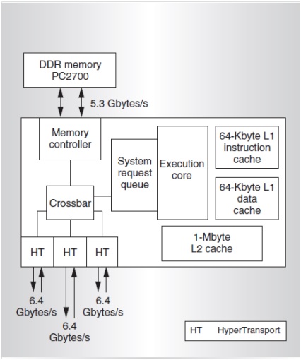
AMD Opteron was the AMD’s first-generation dual core which had 2 distinct K8 cores together on a single die. Cache coherence produces bigger problems on such multiprocessors. It was necessary to use an appropriate coherence protocol to address this problem. The Intel Xeon, which was the competitive counterpart from Intel used the MESI protocol to handle cache coherence. MESI came with the drawback of using much time and bandwidth in certain situations.
MOESI was the AMD’s answer to this problem. MOESI added a fifth state to MESI protocol called “Owned” . MOESI addresses the bandwidth problem faced in MESI protocol when processor having invalid data in its cache wants to modify the data. The processor seeking the data access will have to wait for the processor which modified this data to write back to the main memory, which takes time and bandwidth. This drawback is removed in MOESI by allowing dirty sharing. When the data is held by a processor in the new state “Owned”, it can provide other processors the modified data without or even before writing it to the main memory. This is called dirty sharing. The processor with the data in "Owned" stays responsible to update the main memory later when the cache line is evicted.
MOESI has become one of the most popular snoop-based protocols supported in the AMD64 architecture. The AMD dual-core Opteron can maintain cache coherence in systems up to 8 processors using this protocol.
The five different states of the MOESI protocol are:
- Modified (M) : The most recent copy of the data is present in the cache line. But it is not present in any other processor cache.
- Owned (O) : The cache line has the most recent correct copy of the data . This can be shared by other processors. The processor in this state for this cache line is responsible to update the correct value in the main memory before it gets evicted.
- Exclusive (E) : A cache line holds the most recent, correct copy of the data, which is exclusively present on this processor and a copy is present in the main memory.
- Shared (S) : A cache line in the shared state holds the most recent, correct copy of the data, which may be shared by other processors.
- Invalid (I) : A cache line does not hold a valid copy of the data.
A detailed explanation of this protocol implementation on AMD processor can be found in the manual Architecture of the AMD 64-bit core
The following table summarizes the MOESI protocol:
| Cache Line State: | Modified | Owner | Exclusive | Shared | Invalid |
| This cache line is valid? | Yes | Yes | Yes | Yes | No |
| The memory copy is… | out of date | out of date | valid | valid | - |
| Copies exist in caches of other processors? | No | No | Yes (out of date values) | Maybe | Maybe |
| A write to this line | does not go to bus | does not go to bus | does not go to bus | goes to bus and updates cache | goes directly to bus |
State transition diagram for MOESI protocol is shown below. The top part shows the response to processor-side requests and the bottom part is the response to snooper-side requests. [21]
Real Architectures using Synapse
Implementation Complexities
When implementing the MOESI protocol on a real architecture like AMD K10 series, some modification or optimization was made to the protocol which allowed more efficient operation for some specific program patterns. For example AMD Phenom family of microprocessors (Family 0×10) which is AMD’s first generation to incorporate 4 distinct cores on a single die, and the first to have a cache that all the cores share, uses the MOESI protocol with some optimization techniques incorporated.
It focuses on a small subset of compute problems which behave like Producer and Consumer programs. In such a computing problem, a thread of a program running on a single core produces data, which is consumed by a thread that is running on a separate core. With such programs, it is desirable to get the two distinct cores to communicate through the shared cache, to avoid round trips to/from main memory. The MOESI protocol that the AMD Phenom cache uses for cache coherence can also limit bandwidth. Hence by keeping the cache line in the ‘M’ state for such computing problems, we can achieve better performance.
When the producer thread , writes a new entry, it allocates cache-lines in the modified (M) state. Eventually, these M-marked cache lines will start to fill the L3 cache. When the consumer reads the cache line, the MOESI protocol changes the state of the cache line to owned (O) in the L3 cache and pulls down a shared (S) copy for its own use. Now, the producer thread circles the ring buffer to arrive back to the same cache line it had previously written. However, when the producer attempts to write new data to the owned (marked ‘O’) cache line, it finds that it cannot, since a cache line marked ‘O’ by the previous consumer read does not have sufficient permission for a write request (in the MOESI protocol). To maintain coherence, the memory controller must initiate probes in the other caches (to handle any other S copies that may exist). This will slow down the process.
Thus, it is preferable to keep the cache line in the ‘M’ state in the L3 cache. In such a situation, when the producer comes back around the ring buffer, it finds the previously written cache line still marked ‘M’, to which it is safe to write without coherence concerns. Thus better performance can be achieved by such optimization techniques to standard protocols when implemented in real machines.
You can find more information on how this is implemented and various other ways of optimizations in this manual Software Optimization guide for AMD 10h Processors
Dragon Protocol
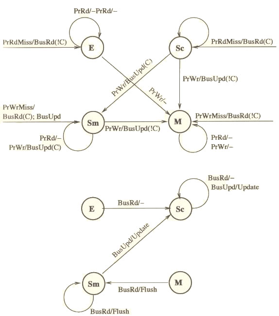
The Dragon Protocol is an update based coherence protocol which does not invalidate other cached copies like what we have seen in the coherence protocols so far. Write propagation is achieved by updating the cached copies instead of invalidating them. But the Dragon Protocol does not update memory on a cache to cache transfer and delays the memory and cache consistency until the data is evicted and written back, which saves time and lowers the memory access requirements. Moreover only the written byte or the word is communicated to the other caches instead of the whole block which further reduces the bandwidth usage. It has the ability to detect dynamically, the sharing status of a block and use a write through policy for shared blocks and write back for currently non-shared blocks. The Dragon Protocol employs the following four states for the cache blocks: Shared Clean, Shared Modified, Exclusive and Modified.
- Modified (M) and Exclusive (E) - these states have the same meaning as explained in the protocols above.
- Shared Modified (Sm) - Only one cache line in the system can be in the Shared Modified state. Potentially two or more caches have this block and memory may or may not be up to date and this processor's cache had modified the block.
- Shared Clean (Sc) - Potentially two or more caches have this block and memory may or may not be up to date (if no other cache has it in Sm state, memory will be up to date else it is not).
When a Shared Modified line is evicted from the cache on a cache miss only then is the block written back to the main memory in order to keep memory consistent. For more information on Dragon protocol, refer to Solihin textbook, page number 229. The state transition diagram has been given below for reference.[21]
The Dragon protocol implements snoopy caches that provided the appearance of a uniform memory space to multiple processors. Here, each cache listens to 2 buses: the processor bus and the memory bus. The caches are also responsible for address translation, so the processor bus carries virtual addresses and the memory bus carries physical addresses. The Dragon system was designed to support 4 to 8 Dragon processors.
Instruction Prefetching
In standard CPU pipelining, the optimization of instruction prefetching is used to minimize the time the CPU spends waiting on instructions being fetched from main memory. Prefetching works perfectly on completely linear programs; but on programs with branches, other optimizations (like branch prediction) have to be implemented, and the cost of branching the wrong has to be considered. source: http://dictionary.reference.com/browse/instruction+prefetch
SOURCE : Yan Solihin, "Fundamentals of Parallel Computer Architecture," Solihin Publishing & Consulting LLC, 2008, pp. 168-173.
SOURCE states that many processors rely on software to implement the prefetch special instruction. SOURCE also mentions that effective prefecthing is characterized by coverage (the fraction of initial cache misses prefetch has transitioned into cache hits), accuracy (the fraction of prefetches that generated cache hits), and timeliness (how early the prefetch arrives). Prefetch buffers help prefetching obtain the desired characteristics.
SOURCE : David F. Kotz and Carla Schlatter Ellis, "Prefetching in File Systems for MIMD Multiprocessors," in IEEE Transactions on Parallel and Distributed Systems, Vol. 1, No. 2, April 1990, pp. 218-230.
Prefetching's optimization is that it brings additional blocks into cache that are surrounding blocks currently being hit by the processor. SOURCE states that simply increasing the hit ratio does not automatically improve overall performance in multiprocessor computation. Prefetching can actually produce stalls on individual CPUs of multiprocessor systems, as the hit ratio benefit will only apply to the thread currently benefiting from the prefetch, and it will have to wait for other threads to catch up. SOURCE suggests that overlapping prefetching decision-making time with user process time as much as possible to minimize the impact of the overall execution sequence as one attempt to implement prefetching within multiprocessor systems.
CMP Implementation in Intel Architecture
Let us now see how Intel architecture using the MESI protocol progressed from a uniprocessor architecture to a Chip MultiProcessor (CMP) using the bus as the interconnect.
Uniprocessor Architecture
The diagram below shows the structure of the memory cluster in Intel Pentium M processor.
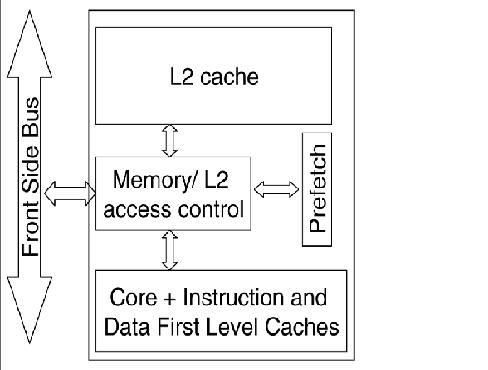
In this structure we have,
- A unified on-chip L1 cache with the processor/core,
- A Memory/L2 access control unit, through which all the accesses to the L2 cache, main memory and IO space are made,
- The second level L2 cache along with the prefetch unit and
- Front side bus (FSB), a single shared bi-directional bus through which all the traffic is sent across.These wide buses bring in multiple data bytes at a time.
As Intel explains it, using this structure, the processor requests were first sought in the L2 cache and only on a miss, were they forwarded to the main memory via the front side bus (FSB). The Memory/L2 access control unit served as a central point for maintaining coherence within the core and with the external world. It contains a snoop control unit that receives snoop requests from the bus and performs the required operations on each cache (and internal buffers) in parallel. It also handles RFO requests (BusUpgr) and ensures the operation continues only after it guarantees that no other version on the cache line exists in any other cache in the system.
CMP Architecture
For CMP implementation, Intel chose the bus-based architecture using snoopy protocols vs the directory protocol because though directory protocol reduces the active power due to reduced snoop activity, it increased the design complexity and the static power due to larger tag arrays. Since Intel has a large market for the processors in the mobility family, directory-based solution was less favorable since battery life mainly depends on static power consumption and less on dynamic power. Let us examine how CMP was implemented in Intel Core Duo, which was one of the first dual-core processor for the budget/entry-level market. The general CMP implementation structure of the Intel Core Duo is shown below
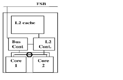
This structure has the following changes when compared to the uniprocessor memory cluster structure.
- L1 cache and the processor/core structure is duplicated to give 2 cores.
- The Memory/L2 access control unit is split into 2 logical units: L2 controller and bus controller. The L2 controller handles all requests to the L2 cache from the core and the snoop requests from the FSB. The bus controller handles data and I/O requests to and from the FSB.
- The prefetching unit is extended to handle the hardware prefetches for each core separately.
- A new logical unit (represented by the hexagon) was added to maintain fairness between the requests coming from the different cores and hence balance the requests to L2 and memory.
This new partitioned structure for the memory/L2 access control unit enhanced the performance while reducing power consumption. For more information on uniprocessor and multiprocessor implementation under the Intel architecture, refer to CMP Implementation in Intel Core Duo Processors
The Intel bus architecture has been evolving in order to accommodate the demands of scalability while using the same MESI protocol; From using a single shared bus to dual independent buses (DIB) doubling the available bandwidth and to the logical conclusion of DIB with the introduction of dedicated high-speed interconnects (DHSI). The DHSI-based platforms use four FSBs, one for each processor in the platform. In both DIB and DHSI, the snoop filter was used in the chipset to cache snoop information, thereby significantly reducing the broadcasting needed for the snoop traffic on the buses. With the production of processors based on next generation 45-nm Hi-k Intel Core microarchitecture, the Intel Xeon processor fabric will transition from a DHSI, with the memory controller in the chipset, to a distributed shared memory architecture using Intel QuickPath Interconnects using MESIF protocol.
Word Invalidation
One complexity problem applying to a number of the protocols deals with invalidation. In newer protocols, individual words may be modified in a cache line, as opposed to the entirety of the line. The other processors will thus have a mostly correct cache line, with only a word difference. This leads to potential complexity, because to 'correct' the error the other processors must transition from shared to invalid, where they then can read the correct word from the bus and place it back into the line, transitioning back into shared. This transition is potentially unnecessary, as the second processor may never access the specific word changed, but it may access other words in the cache line. One potential solution to this is being researched at the present time, advancing the protocols so that a cache line is "not invalidated on the first dirty word, but after the number of dirty words crosses some predetermined value, which is data type and application dependent." In other words, if the application can possibly have multiple words 'incorrect,' several transitions to and from the invalid state may be avoided.
Source: http://tab.computer.org/tcca/NEWS/sept96/dsmideas.ps
In essence, the solution proposed here is to advance the MOESI protocol with word invalidation and specific treatment of temporal and spatial data, so that the block is not invalidated.
Performance: MOESI vs MEI/MESI
Early multiprocessors (such as the PowerPC processors) were designed to work with three states (Modified, Exclusive, Invalid - this is similar to the MSI protocol discussed earlier, the term MEI is used to remain consistent with the sources used for reference). As time progressed, more multi-processors transitioned to the MESI protocol. This is most likely due to the characteristics of MEI - it is "easy to implement but leads to inefficiencies in the way that memory bus bandwidth is used" source. As a result, systems with two or more MEI processors (most likely) will not see the 'full' potential of the extra processors, due to the inefficient bus transactions.
In contrast, the five-state protocol MOESI is more complex to implement than MESI and MEI/MSI. However, advantages arise from using it. As Any Keane (VP of Marketing for PMC-Sierra) put it "this [fifth] state allows shared data that is dirty to remain in the cache. Without this state, any shared line would be written back to memory to change the original state form modified. Since we have a dedicated, fast path from CPU to CPU, this state maximizes the use of this path rather than the path to memory, which is inherently slower" source. This advantage can be implemented by allowing MOESI to make some processor to processor transfers from level 2 caches.
References
- Cache coherence
- Introduction to QuickPath Interconnect
- CMP Implementation in Intel Core Duo Processors
- Common System Interface in Intel Processors
- Cache consistency with MESI on Intel processor
- AMD dual core Architecture
- AMD64 Architecture Programmer's manual
- Software Optimization guide for AMD 10h Processors
- Architecture of AMD 64 bit core
- Silicon Graphics Computer Systems
- Parallel computer architecture: a hardware/software approach By David E. Culler, Jaswinder Pal Singh, Anoop Gupta
- Three state invalidation protocols
- Synapse tightly coupled multiprocessors: a new approach to solve old problems
- Coherence protocols: evaluation using a multiprocessor simulation model
- Dragon Protocol
- Xerox Dragon
- Coherence Protocols
- XDBus
- ARM
- IBM POWER4
- Fundamentals of Parallel Computer Architecture: Multichip and Multicore Systems. Solihin, Yan
- Intel Itanium 2
- MESI-MESI-MOESI Banana-fana...
- RSIM
- Synapse tightly coupled multiprocessors