CSC/ECE 506 Spring 2010/12 EC: Difference between revisions
No edit summary |
No edit summary |
||
| Line 1: | Line 1: | ||
<h1>Interconnection Network Architecture </h1> | <h1>Interconnection Network Architecture </h1> | ||
<p> | <p> | ||
| Line 22: | Line 20: | ||
<h1>Types of Network Topologies </h1> | <h1>Types of Network Topologies </h1> | ||
<h2>Linear Array</h2> | |||
<p> | <p> | ||
[[Image:Top_linear.jpg]] | [[Image:Top_linear.jpg]] | ||
| Line 31: | Line 29: | ||
<br> | <br> | ||
<h2>Ring</h2> | |||
<p> | <p> | ||
[[Image:Top_ring.jpg]] | [[Image:Top_ring.jpg]] | ||
| Line 40: | Line 38: | ||
<br> | <br> | ||
<h2>2-D Mesh</h2> | |||
<p> | <p> | ||
[[Image:Top_2Dmesh.jpg]] | [[Image:Top_2Dmesh.jpg]] | ||
| Line 49: | Line 47: | ||
<br> | <br> | ||
<h2>2-D Torus</h2> | |||
<p> | <p> | ||
[[Image:Top_2Dtorus.jpg]] | [[Image:Top_2Dtorus.jpg]] | ||
| Line 58: | Line 56: | ||
<br> | <br> | ||
<h2>Cube</h2> | |||
<p> | <p> | ||
[[Image:Top_cube.jpg]] | [[Image:Top_cube.jpg]] | ||
| Line 67: | Line 65: | ||
<br> | <br> | ||
<h2>Hypercube</h2> | |||
<p> | <p> | ||
[[Image:Top_hypercube.jpg]] | [[Image:Top_hypercube.jpg]] | ||
| Line 76: | Line 74: | ||
<br> | <br> | ||
<h2>Tree</h2> | |||
<p> | <p> | ||
[[Image:Top_tree.jpg]] | [[Image:Top_tree.jpg]] | ||
| Line 85: | Line 83: | ||
<br> | <br> | ||
<h2>Fat Tree</h2> | |||
<p> | <p> | ||
[[Image:Top_fat_tree.jpg]] | [[Image:Top_fat_tree.jpg]] | ||
| Line 94: | Line 92: | ||
<br> | <br> | ||
<h2>Butterfly</h2> | |||
<p> | <p> | ||
[[Image:Top_butterfly.jpg]] | [[Image:Top_butterfly.jpg]] | ||
| Line 123: | Line 121: | ||
[[Image:Disknet_network.jpg]] | [[Image:Disknet_network.jpg]] | ||
<br> | <br> | ||
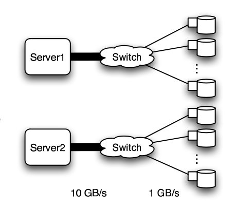
''Basic structure of Hospodor and Miller's experimental network''<sup>2</sup> | |||
</p> | </p> | ||
<br> | <br> | ||
<h2>Fat Tree</h2> | |||
<p> | <p> | ||
In large scale, high performance applications, fat tree can be a choice. However, in order to "fatten" up the links, redundant connections must be used. Instead of using one link between switching nodes, several must be used. The problem with this is that with more input and output links, one would need routers with more input and output ports. Router with excess of 100 ports are difficult to build and expensive, so multiple routers would have to be stacked together. Still, the routers would be expensive and would require several of them<sup>2</sup>. | In large scale, high performance applications, fat tree can be a choice. However, in order to "fatten" up the links, redundant connections must be used. Instead of using one link between switching nodes, several must be used. The problem with this is that with more input and output links, one would need routers with more input and output ports. Router with excess of 100 ports are difficult to build and expensive, so multiple routers would have to be stacked together. Still, the routers would be expensive and would require several of them<sup>2</sup>. | ||
| Line 133: | Line 132: | ||
<br> | <br> | ||
<h2>Butterfly</h2> | |||
<p> | <p> | ||
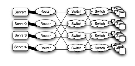
In high performance applications, the butterfly structure is a good choice. The butterfly topology uses fewer links than other topologies, however, each link carries traffic from the entire layer. Fault tolerance is poor. There exists only a single path between pairs of nodes. Should the link break, data cannot be re-routed, and communication is broken<sup>2</sup>. | In high performance applications, the butterfly structure is a good choice. The butterfly topology uses fewer links than other topologies, however, each link carries traffic from the entire layer. Fault tolerance is poor. There exists only a single path between pairs of nodes. Should the link break, data cannot be re-routed, and communication is broken<sup>2</sup>. | ||
<br> | <br> | ||
[[Image:Disknet_butterfly.jpg]] | [[Image:Disknet_butterfly.jpg]] | ||
<br> | |||
''Butterfly structure''<sup>2</sup> | |||
</p> | </p> | ||
<br> | <br> | ||
<h2>Meshes and Torii</h2> | |||
<p> | <p> | ||
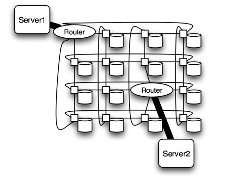
The mesh and torus structure used in this application would require a large number of links and total aggregate of several thousands of ports. However, since there are so many links, the mesh and torus structures provide alternates paths in case of failures<sup>2</sup>. | The mesh and torus structure used in this application would require a large number of links and total aggregate of several thousands of ports. However, since there are so many links, the mesh and torus structures provide alternates paths in case of failures<sup>2</sup>. | ||
<br> | |||
<br> | <br> | ||
[[Image:Disknet_mesh.jpg]] | [[Image:Disknet_mesh.jpg]] | ||
<br> | |||
''Mesh structure''<sup>2</sup> | |||
<br> | |||
<br> | <br> | ||
[[Image:Disknet_torus.jpg]] | [[Image:Disknet_torus.jpg]] | ||
<br> | |||
''Torus structure''<sup>2</sup> | |||
</p> | </p> | ||
<br> | <br> | ||
<h2>Hypercube</h2> | |||
<p> | <p> | ||
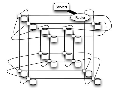
Similar to the torii structures, the hypercube requires larger number of links. However, the bandwidth scales better than mesh and torii structures. | Similar to the torii structures, the hypercube requires larger number of links. However, the bandwidth scales better than mesh and torii structures. | ||
<br> | |||
<br> | <br> | ||
[[Image:Disknet_hypercube.jpg]] | [[Image:Disknet_hypercube.jpg]] | ||
<br> | |||
''Hypercube structure''<sup>2</sup> | |||
</p> | </p> | ||
<br> | <br> | ||
| Line 163: | Line 173: | ||
<p> | <p> | ||
The following table shows the total number of ports required for each network topology. | The following table shows the total number of ports required for each network topology. | ||
<br> | |||
<br> | <br> | ||
[[Image:Disknet_ports.jpg]] | [[Image:Disknet_ports.jpg]] | ||
<br> | <br> | ||
''Number of ports for each topology''<sup>2</sup> | |||
</p> | </p> | ||
<br> | |||
<p> | <p> | ||
As the figure above shows, the 6-D hypercube requires the largest number of ports, due to its relatively complex six-dimensional structure. In contrast, the fat tree requires the least number of ports, even though links have been "fattened" up by using redundant links. The butterfly network requires more than twice the number of ports as the fat tree, since it essentially replicates the switching layer of the fat tree. The number of ports for the mesh and torii structures increase as the dimensionality increases. | As the figure above shows, the 6-D hypercube requires the largest number of ports, due to its relatively complex six-dimensional structure. In contrast, the fat tree requires the least number of ports, even though links have been "fattened" up by using redundant links. The butterfly network requires more than twice the number of ports as the fat tree, since it essentially replicates the switching layer of the fat tree. The number of ports for the mesh and torii structures increase as the dimensionality increases. | ||
<br> | <br> | ||
<br> | |||
Below the average path length, or average number of hops, and the average link load (GB/s) is shown. | Below the average path length, or average number of hops, and the average link load (GB/s) is shown. | ||
<br> | |||
<br> | <br> | ||
[[Image:Disknet_load.jpg]] | [[Image:Disknet_load.jpg]] | ||
<br> | <br> | ||
''Average path length and link load for each topology''<sup>2</sup> | |||
</p> | </p> | ||
<br> | |||
<p> | <p> | ||
Looking at the trends, when average path length is high, the average link load is also high. In other words, average path length and average link load are proportionally related. It is obvious from the graph that 2-D mesh has, by far, the worst performance. In a large network such as this, the average path length is just too high, and the average link load suffers. For this type of high-performance network, the 2-D mesh does not scale well. Likewise the 2-D torus cuts the average path length and average link load in half by connected the edge nodes together, however, the performance compared to other types is relatively poor. The butterfly and fat-tree have the least average path length and average link load. | Looking at the trends, when average path length is high, the average link load is also high. In other words, average path length and average link load are proportionally related. It is obvious from the graph that 2-D mesh has, by far, the worst performance. In a large network such as this, the average path length is just too high, and the average link load suffers. For this type of high-performance network, the 2-D mesh does not scale well. Likewise the 2-D torus cuts the average path length and average link load in half by connected the edge nodes together, however, the performance compared to other types is relatively poor. The butterfly and fat-tree have the least average path length and average link load. | ||
<br> | <br> | ||
<br> | |||
The figure below shows the cost of the network topologies. | The figure below shows the cost of the network topologies. | ||
<br> | |||
<br> | <br> | ||
[[Image:Disknet_cost.jpg]] | [[Image:Disknet_cost.jpg]] | ||
<br> | <br> | ||
''Cost of each topology''<sup>2</sup> | |||
</p> | </p> | ||
<br> | |||
<p> | <p> | ||
Despite using the fewest number of ports, the fat tree topology has the highest cost, by far. Although it uses the fewest ports, the ports are high bandwidth ports of 10 GB/s. Over 2400, ports of 10 GB/s are required have enough bandwidth at the upper levels of the tree. This pushes the cost up dramatically, and from a cost standpoint is impractical. While the total cost of fat tree is about 15 million dollars, the rest of the network topologies are clustered below 4 million dollars. When the dimensionalality of the mesh and torii structures increase, the cost increases. The butterfly network costs between the 2-D mesh/torii and the 6-D hypercube. | Despite using the fewest number of ports, the fat tree topology has the highest cost, by far. Although it uses the fewest ports, the ports are high bandwidth ports of 10 GB/s. Over 2400, ports of 10 GB/s are required have enough bandwidth at the upper levels of the tree. This pushes the cost up dramatically, and from a cost standpoint is impractical. While the total cost of fat tree is about 15 million dollars, the rest of the network topologies are clustered below 4 million dollars. When the dimensionalality of the mesh and torii structures increase, the cost increases. The butterfly network costs between the 2-D mesh/torii and the 6-D hypercube. | ||
<br> | <br> | ||
<br> | |||
When the cost and average link load is factored the following graph is produced. | When the cost and average link load is factored the following graph is produced. | ||
<br> | |||
<br> | <br> | ||
[[Image:Disknet_overall.jpg]] | [[Image:Disknet_overall.jpg]] | ||
<br> | <br> | ||
''Overall cost of each topology''<sup>2</sup> | |||
</p> | </p> | ||
<br> | |||
<p> | |||
From the figure above, the 6-D hypercube demonstrates the most cost effective choice on this particular network setup. Although the 6-D hypercube costs more because it needs more links and ports, it provides higher bandwidth, which can offset the higher cost. The high dimensional torii also perform well, but cannot provide as much bandwidth as the 6-D hypercube. For systems that do not need as much bandwidth, the high-dimensional torii is also a good choice. The butterfly topology is also an alternative, but has lower fault tolerance. | |||
</p> | |||
<h1>Routing</h1> | |||
<p> | <p> | ||
The routing algorithm determines what path a packet of data will take from source to destination. Routing can be deterministic, where the path is the same given a source and destination, or adaptive, where the path can change. The routing algorithm can also be partially adaptive where packets have multiple choices, but does not allow all packets to use the shortest path<sup>3</sup>. | |||
</p> | </p> | ||
<h2>Deadlock</h2> | |||
<p> | |||
When packets are in '''deadlock''' when they cannot continue to move through the nodes. The illustration below demonstrates this event. | |||
<br> | |||
<br> | |||
[[Image:Routing_deadlock.jpg]] | |||
<br> | |||
''Example of deadlock'' | |||
<br> | |||
<br> | |||
Assume that all of the buffers are full at each node. Packet from Node 1 cannot continue to Node 2. The packet from Node 2 cannot continue to Node 3, and so on. Since packet cannot move, it is deadlocked. | |||
<br> | |||
<br> | |||
The deadlock occurs from cyclic pattern of routing. To avoid deadlock, avoid circular routing pattern. | |||
<br> | |||
<br> | |||
To avoid circular patterns of routing, some routing patterns are disallowed. These are called '''turn restrictions''', where some turns are not allowed in order to avoid making a circular routing pattern. Some of these turn restrictions are mentioned below. | |||
Revision as of 19:46, 22 April 2010
Interconnection Network Architecture
In a multi-processor system, processors need to communicate with each other and access each other's resources. In order to route data and messages between processors, an interconnection architecture is needed.
Typically, in a multiprocessor system, message passed between processors are frequent and short1. Therefore, the interconnection network architecture must handle messages quickly by having low latency, and must handle several messages at a time and have high bandwidth.
In a network, a processor along with its cache and memory is considered a node. The physical wires that connect between them is called a link. The device that routes messages between nodes is called a router. The shape of the network, such as the number of links and routers, is called the network topology.
Types of Network Topologies
Linear Array

The nodes are connected linearly as in an array. This type of topology is simple, however, it does not scale well. The longest distance between two nodes, or the diameter, is equivalent to the number of nodes.
Ring
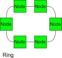
Similar structure as the linear array, except, the ending nodes connect to each other, establishing a circular structure. The longest distance between two nodes is cut in half.
2-D Mesh
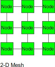
The 2-D mesh can be thought of as several linear arrays put together to form a 2-dimensional structure. Nodes that are not on the edge have 4 input or output links, or a degree of 4.
2-D Torus
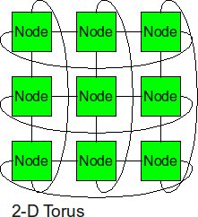
The 2-D torus takes the structure of the 2-D mesh and connects the nodes on the edges. This decreases the diameter, but the number of links is higher.
Cube
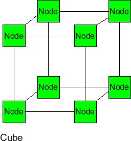
The cube can be thought of as a three-dimensional mesh.
Hypercube
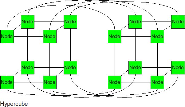
The hypercube is essentially multiple cubes put together.
Tree
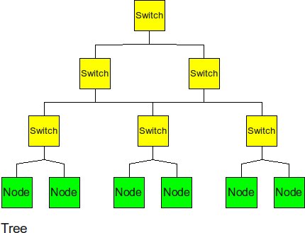
The tree is a hierarchical structure nodes on the bottom and switching nodes at the upper levels. The tree experiences high traffic at the upper levels.
Fat Tree
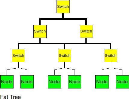
The fat tree alleviates the traffic at upper levels by "fattening" up the links at the upper levels.
Butterfly
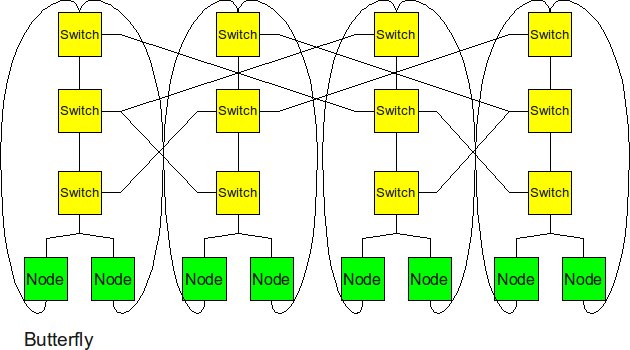
The butterfly structure is similar to the tree structure, but it replicates the switching node structure of the tree topology and connects them together so that there are equal links and routers at all levels.
Real-World Implementation of Network Topologies
In a research study by Andy Hospodor and Ethan Miller, several network topologies were investigated in a high-performance, high-traffic network2. Several topologies were investigated including the fat tree, butterfly, mesh, torii, and hypercube structures. Advantages and disadvantages including cost, performance, and reliability were discussed.
In this experiment, a petabyte-scale network with over 100 GB/s total aggregate bandwidth was investigated. The network consisted of 4096 disks with large servers with routers and switches in between2.
The overall structure of the network is shown below. Note that this structure is very susceptible to failure and congestion.
Basic structure of Hospodor and Miller's experimental network2
Fat Tree
In large scale, high performance applications, fat tree can be a choice. However, in order to "fatten" up the links, redundant connections must be used. Instead of using one link between switching nodes, several must be used. The problem with this is that with more input and output links, one would need routers with more input and output ports. Router with excess of 100 ports are difficult to build and expensive, so multiple routers would have to be stacked together. Still, the routers would be expensive and would require several of them2.
Butterfly
In high performance applications, the butterfly structure is a good choice. The butterfly topology uses fewer links than other topologies, however, each link carries traffic from the entire layer. Fault tolerance is poor. There exists only a single path between pairs of nodes. Should the link break, data cannot be re-routed, and communication is broken2.
Butterfly structure2
Meshes and Torii
The mesh and torus structure used in this application would require a large number of links and total aggregate of several thousands of ports. However, since there are so many links, the mesh and torus structures provide alternates paths in case of failures2.

Mesh structure2
Torus structure2
Hypercube
Similar to the torii structures, the hypercube requires larger number of links. However, the bandwidth scales better than mesh and torii structures.
Hypercube structure2
Comparison of Network Topologies
The following table shows the total number of ports required for each network topology.
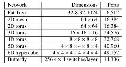
Number of ports for each topology2
As the figure above shows, the 6-D hypercube requires the largest number of ports, due to its relatively complex six-dimensional structure. In contrast, the fat tree requires the least number of ports, even though links have been "fattened" up by using redundant links. The butterfly network requires more than twice the number of ports as the fat tree, since it essentially replicates the switching layer of the fat tree. The number of ports for the mesh and torii structures increase as the dimensionality increases.
Below the average path length, or average number of hops, and the average link load (GB/s) is shown.
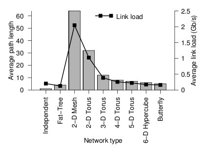
Average path length and link load for each topology2
Looking at the trends, when average path length is high, the average link load is also high. In other words, average path length and average link load are proportionally related. It is obvious from the graph that 2-D mesh has, by far, the worst performance. In a large network such as this, the average path length is just too high, and the average link load suffers. For this type of high-performance network, the 2-D mesh does not scale well. Likewise the 2-D torus cuts the average path length and average link load in half by connected the edge nodes together, however, the performance compared to other types is relatively poor. The butterfly and fat-tree have the least average path length and average link load.
The figure below shows the cost of the network topologies.
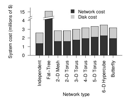
Cost of each topology2
Despite using the fewest number of ports, the fat tree topology has the highest cost, by far. Although it uses the fewest ports, the ports are high bandwidth ports of 10 GB/s. Over 2400, ports of 10 GB/s are required have enough bandwidth at the upper levels of the tree. This pushes the cost up dramatically, and from a cost standpoint is impractical. While the total cost of fat tree is about 15 million dollars, the rest of the network topologies are clustered below 4 million dollars. When the dimensionalality of the mesh and torii structures increase, the cost increases. The butterfly network costs between the 2-D mesh/torii and the 6-D hypercube.
When the cost and average link load is factored the following graph is produced.
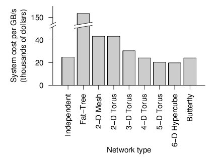
Overall cost of each topology2
From the figure above, the 6-D hypercube demonstrates the most cost effective choice on this particular network setup. Although the 6-D hypercube costs more because it needs more links and ports, it provides higher bandwidth, which can offset the higher cost. The high dimensional torii also perform well, but cannot provide as much bandwidth as the 6-D hypercube. For systems that do not need as much bandwidth, the high-dimensional torii is also a good choice. The butterfly topology is also an alternative, but has lower fault tolerance.
Routing
The routing algorithm determines what path a packet of data will take from source to destination. Routing can be deterministic, where the path is the same given a source and destination, or adaptive, where the path can change. The routing algorithm can also be partially adaptive where packets have multiple choices, but does not allow all packets to use the shortest path3.
Deadlock
When packets are in deadlock when they cannot continue to move through the nodes. The illustration below demonstrates this event.
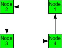
Example of deadlock
Assume that all of the buffers are full at each node. Packet from Node 1 cannot continue to Node 2. The packet from Node 2 cannot continue to Node 3, and so on. Since packet cannot move, it is deadlocked.
The deadlock occurs from cyclic pattern of routing. To avoid deadlock, avoid circular routing pattern.
To avoid circular patterns of routing, some routing patterns are disallowed. These are called turn restrictions, where some turns are not allowed in order to avoid making a circular routing pattern. Some of these turn restrictions are mentioned below.