CSC/ECE 506 Fall 2007/wiki4 001 a1: Difference between revisions
No edit summary |
|||
| (67 intermediate revisions by the same user not shown) | |||
| Line 5: | Line 5: | ||
== Gigabit Ethernet == | == Gigabit Ethernet == | ||
[[Image:jdbramanpic1.jpg]] | |||
Gigabit Ethernet is by far the communications choice for small, lower-powered clusters with a minimal need for communications. Ethernet is defined by IEEE Standard 802.3. It is implemented by networking protocols that allow 1GB of data to be transfered at a speed of up to 1 GB per second. 1 GB Ethernet is currently being replaced in the marketplace with the faster 10GB Ethernet. The standard defines the use of data frame collision detection rather than collision avoidance. CSMA/CD is used to describe the method Ethernet protocols allow communication. This stands for Carrier Sense Multiple Access with Collision Detection. If two stations operating Gigabit Ethernet send data frames which collide, the following protocol is followed according to Standard 802.3: | |||
Main procedure | |||
1. Frame ready for transmission. | |||
2. Is medium idle? If not, wait until it becomes ready and wait the interframe gap period (9.6 µs in 10 Mbit/s Ethernet). | |||
3. Start transmitting. | |||
4. Does a collision occur? If so, go to collision detected procedure. | |||
5. Reset retransmission counters and end frame transmission. | |||
Collision detected procedure | |||
1. Continue transmission until minimum packet time is reached (jam signal) to ensure that all receivers detect the collision. | |||
2. Increment retransmission counter | |||
3. Is maximum number of transmission attempts reached? If so, abort transmission. | |||
4. Calculate and wait random backoff period based on number of collisions. | |||
5. Re-enter main procedure at stage 1. | |||
The most common Ethernet frame format (Type II) includes bits for source MAC address, destination MAC address, ether type, payload, and checksum. MAC (Media Access Control) is a layer 2 protocol that works below the Ethernet 802.2 LLC (Logical Link Control) and above the physical layer in most network topologies. Ethernet interfaces with MAC and LLC in the data link layer below the network layer. The following is a diagram Etherent data frame format: | |||
[[Image:jdbramanpic2.jpg]] | |||
Supercomputers connected by Ethernet can choose to use on of many physical layer links and network layer types. TCP/IP is the most common network layer implemented worldwide which is why gigabit Ethernet is so prevalent. Less modification has to take place for usability in large scale supercomputer networks. Many of the other most implemented supercomputer interconnects are simply custom implementations of the network layer type. This is done to speed up Ethernet LAN clusters running on the data link layer since TCP/IP can have too much latency and poor reliability. | |||
== Infiniband == | == Infiniband == | ||
= | Infiniband is a conglomeration of the Future I/O interconnect designed by Compaq, IBM and HP with the Next Generation I/O developed by Intel, Microsoft and Sun. These companies along with nearly 220 corporate members of the Infiniband Trade Association (IBTA) have come to support the adoptance of the Infiniband technology. | ||
Infiniband is a switched fabric interconnect that parallels all layers of networking to reduce latencies and connect networks regardless of their interconnect topology. An Infiniband network layer operation diagram is shown below: | |||
[[Image:ib_layers2.jpg]] | |||
To reduce TCP/IP latencies, a large portion of the TCP/IP protocol stack execution is offloaded onto the client's ethernet NIC card. A subnet of switches and end users can communicate to any other Infiniband subnet via TCP/IP routers. In the message-passing based Infiniband Transport Layer, Queue Pairs (QP) are created. They are pairs because one queue is inbound and one is outbound. The QP is the mechanism by which quality of service, system protection, error detection and response, and allowable services are defined. Creating a QP does require support from the operating system. Associated with each QP is a region of memory to be used for buffers, a key that must match on each incoming packet (the Q_Key) to verify the validity of the packet, and potentially a partition key specifying which portion of the fabric may be accessed by this QP. Allowing only a particular portion of a fabric to be available to a client prevents a renegade process from destroying kernel/memory address space and allows other processes operating on other memory portions to continue uninterupted operation. The following operations are possible between Queue Pairs: | |||
Send – Includes a scatter/gather capability. | |||
RDMA-Write – Remote Direct Memory Access from local to remote memory. | |||
RDMA-Read – Remote Direct Memory Access from remote to local memory. | |||
Atomic Operations – Compare & Swap and Fetch & Add in remote memory. | |||
Four types of Transport Layer connections are defined for Infiniband. They are a Reliable Connection (RC), Unreliable Connection (UC), Unreliable Datagram (UD), and Reliable Datagram (RD). These provide various quality of service (QoS) and error recovery characteristics. | |||
Links are 8B/10B encoded, meaning they carry 8B of data for every 10B transmitted. So Serial Data Rate Infiniband which operates at 2.5 GBps signalling provides 2Gbps of actual data transmission. Data can be sent in the form of 5 message types t0/from a host channel adapter (HCA) at the processor to/from a taget channel adapter (TCA) at a peripheral I/O element. Between the two adapters, messages traverse Infiniband switches and descend to network layer routers if necessary to get to other subnets. The data messages are comprised of packets. A data message must take one of the forms accepted by queue pairs. | |||
An example of an Infiniband network is shown below. | |||
[[Image:ib1.jpg]] | |||
Unlike switches which forward based only on the Local Route Header (LRH), routers read the Global Route Header to forward messages to the correct subnet. Once at the appropriate subnet, the router rebuilds each packet in the message with the appropriate Local Identifier (LID). The standard Infiniband data packet header order is defined as follows: | |||
[[Image:jdbramanpic3.jpg]] | |||
LRH - Local Route Header | |||
GRH - Global Route Header | |||
BTH - Base Transport Header | |||
ExTH - Extended Transport Header | |||
Msg Payload - Message Payload | |||
Immediate Data Header | |||
I-CRC - Invariant CRC (32-bit) | |||
Not used for Raw datagram | |||
V-CRC - Variant CRC (16-bit) | |||
The local route header is added to data to be sent to another end users within a subnet, this form of communication operates exclusively at the data link layer according to LID in the LRH. There are two types of packets sent in this layer, management and data packets. Management packets deal with link configuration and management while data packets transmit up to a 4KB data payload. The LRH is further defined as follows: | |||
[[Image:jdbramanpic4.jpg]] | |||
LRH used to route packets within subnets. | |||
VL - Actual Virtual Lane Used | |||
Vers - LRH Version | |||
NH - Next Header - indicates next header | |||
IBA transport, GRH, IPv6 (raw), Ethertype (raw) | |||
SL - Service Level | |||
Destination LID - Destination Local Identifier (unique only within subnet) | |||
Rsv - Reserve Field | |||
Pkt Len - Packet Length | |||
Source LID - Source Local Identifier | |||
The global route headers is added to data to be sent to an end user on another subnet, its header is further defined as follows: | |||
[[Image:jdbramanpic5.jpg]] | |||
All endnodes are required to source / sink GRH packets | |||
GID (Global Identifier) – valid IPv6 Address | |||
GRH used to route packets between subnets and for multicast | |||
GRH is consistent with IPv6 header per RFC 2460. | |||
TC (Traffic Class) – Communicates end-to-end class of service | |||
Flow ID (Flow Label) – Can be used to identify an end-end flow | |||
Present in all packets if the LRH Next Header = GRH. | |||
Each end node shall be assigned an unique GID | |||
Applications target an end node by its GID | |||
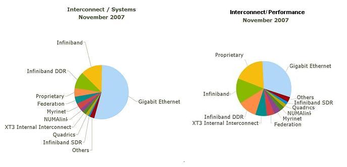
As far as processor efficiency and performance of supercomputer interconnects, Infiniband ranks as the best according to Top500. While Ethernet remains atop the most implemented list due to small scale networks not needing speed as much as low cost scalability in an interconnect, Infiniband is taking a larger portion of the market due to its high performance specs. | |||
[[Image:graphjdbraman.jpg]] | |||
== | === Infiniband DDR === | ||
On the physical layer, Infiniband defines three link speeds, 1x, 4x and 12x. Each link has four wires (two in each direction) that provide full duplex at 2.5Gbps due to a 2.5Gbps signalling rate for Infiniband SDR. | |||
In InfiniBand DDR (Double Data Rate), the signalling rate is increased to 5 Gbits/s, giving a 4x link 16 Gbps data throughput since 10B/8B encoded links can be bonded together for additional bandwidth, and 12x links get a 48 Gbps data throughput, at full duplex. Quad data rate (QDR), demonstrated in 2007 with system production expected in 2008, have a signalling rate of 10 Gbps per lane and can acheive 96 Gbps data throughput on a 12x 10B/8B encoded link. | |||
== Myrinet == | == Myrinet == | ||
== | While IBM's Federation, SGI's NUMAlink and other interconnects are internal physical layer switch topologies built for a particular supercomputer type, Myrinet, like Ethernet and Infiniband, brings a broad network compatability approach to connect supercomputer clusters. | ||
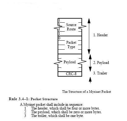
Myrinet is a data link layer interconnect developed by Myricom to replace Ethernet. It can connect clusters of computers and provides 5-10 times lower latency than Ethernet over TCP/IP. It uses a 2.5 Gbit/s link that provides processor offload. It uses lightweight protocols capable of providing more throughput, less interference and latency than Ethernet. Myricom has developed an array of programs to operate on Myrinet interconnects, allowing the host CPU to bypass the operating system in the upper application layers for further reductions in latency. Myrinet packets include a header, payload, and CRC bits. | |||
[[Image:myrinet_update.jpg]] | |||
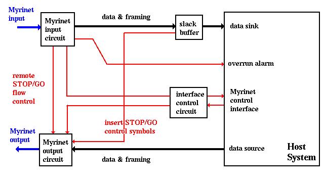
The setup for a Myrinet network is arranged as follows: | |||
[[Image:myrinet_interfaces.jpg]] | |||
==Pros/Cons== | |||
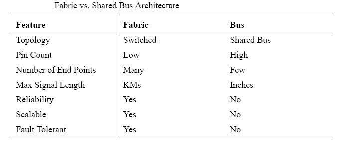
While Myrinet is a valid interconnect still used in some supercomputer networks, the battle for performance and implementation superiority is obviously between Ethernet and Infiniband. The pros and cons of Ethernet's bus based topology vs. Infiniband's switch based topology are shown in the following table: | |||
[[Image:pro_con_table.jpg]] | |||
One drawback to Infiniband is its lack of a formal programming interface standard. While Ethernet is defined by IEEE Standard 802.3, the closest interface standard for Infiniband is the OpenFabrics Alliance verb list which has been adopted by most of the corporate sponsors of Infiniband. | |||
Infiniband has impacted the supercomputer interconnect market so quickly due to its high bandwidth and low latency (200ns) connectivity which has made it the preferred choice for connecting computer nodes into a cluster. The interconnect comparison in the general marketplace continues to be dominated by Ethernet because of its ability to connect other resources, such as remote sites and users’ desktops due to its broad availability and formal standards. | |||
== Sources == | == Sources == | ||
[http://www.top500.org/stats/list/30/conn] top500.org interconnect usage (Share %), performance statistics (Rmax Sum) | [http://www.top500.org/stats/list/30/conn] top500.org interconnect usage (Share %), performance statistics (Rmax Sum) | ||
[http://www.ieee802.org/3/]IEEE 802.3 Ethernet Standard | |||
[http://en.wikipedia.org/wiki/Ethernet] Ethernet protocol summary on Wikipedia | |||
[http://www.byteandswitch.com/document.asp?doc_id=98210] Myrinet article | |||
[http://people.engr.ncsu.edu/efg/506/sum06/lectures/notes/lec12.ppt] Dr. Steve Hunter on Infiniband, NCSU Architecture of Parallel Computers, Lecture 12, 6/12/2006 | |||
[http://www.rtcmagazine.com/home/article.php?id=100387&pg=3] RTC Magazine, Processor Efficiency chart | |||
[http://www.myri.com/open-specs/link-history/index.html] Myrinet open source protocol | |||
[http://www.infinibandta.org/newsroom/whitepapers/intro_to_infiniband_1207.pdf] | |||
IBTA Whitepapers: Intro to Infiniband | |||
[http://www.infinibandta.org/newsroom/whitepapers/sky_InfiniBand_Arch_090602.pdf] IBTA Whitepapers: Enhanced Reliability | |||
Latest revision as of 01:06, 4 December 2007
Current Supercomputer Interconnect Topologies
Gigabit Ethernet
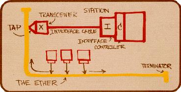
Gigabit Ethernet is by far the communications choice for small, lower-powered clusters with a minimal need for communications. Ethernet is defined by IEEE Standard 802.3. It is implemented by networking protocols that allow 1GB of data to be transfered at a speed of up to 1 GB per second. 1 GB Ethernet is currently being replaced in the marketplace with the faster 10GB Ethernet. The standard defines the use of data frame collision detection rather than collision avoidance. CSMA/CD is used to describe the method Ethernet protocols allow communication. This stands for Carrier Sense Multiple Access with Collision Detection. If two stations operating Gigabit Ethernet send data frames which collide, the following protocol is followed according to Standard 802.3:
Main procedure
  1. Frame ready for transmission.
  2. Is medium idle? If not, wait until it becomes ready and wait the interframe gap period (9.6 µs in 10 Mbit/s Ethernet).
  3. Start transmitting.
  4. Does a collision occur? If so, go to collision detected procedure.
  5. Reset retransmission counters and end frame transmission.
Collision detected procedure
  1. Continue transmission until minimum packet time is reached (jam signal) to ensure that all receivers detect the collision.
  2. Increment retransmission counter
  3. Is maximum number of transmission attempts reached? If so, abort transmission.
  4. Calculate and wait random backoff period based on number of collisions.
  5. Re-enter main procedure at stage 1.
The most common Ethernet frame format (Type II) includes bits for source MAC address, destination MAC address, ether type, payload, and checksum. MAC (Media Access Control) is a layer 2 protocol that works below the Ethernet 802.2 LLC (Logical Link Control) and above the physical layer in most network topologies. Ethernet interfaces with MAC and LLC in the data link layer below the network layer. The following is a diagram Etherent data frame format:
Supercomputers connected by Ethernet can choose to use on of many physical layer links and network layer types. TCP/IP is the most common network layer implemented worldwide which is why gigabit Ethernet is so prevalent. Less modification has to take place for usability in large scale supercomputer networks. Many of the other most implemented supercomputer interconnects are simply custom implementations of the network layer type. This is done to speed up Ethernet LAN clusters running on the data link layer since TCP/IP can have too much latency and poor reliability.
Infiniband
Infiniband is a conglomeration of the Future I/O interconnect designed by Compaq, IBM and HP with the Next Generation I/O developed by Intel, Microsoft and Sun. These companies along with nearly 220 corporate members of the Infiniband Trade Association (IBTA) have come to support the adoptance of the Infiniband technology.
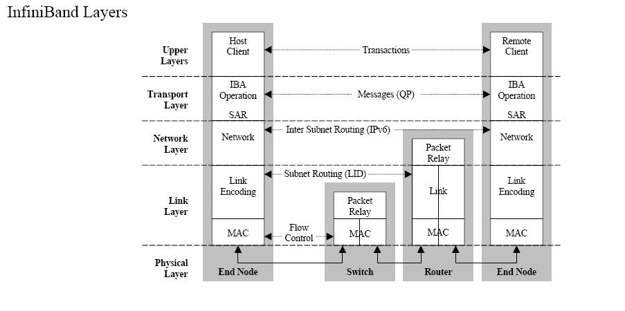
Infiniband is a switched fabric interconnect that parallels all layers of networking to reduce latencies and connect networks regardless of their interconnect topology. An Infiniband network layer operation diagram is shown below:
To reduce TCP/IP latencies, a large portion of the TCP/IP protocol stack execution is offloaded onto the client's ethernet NIC card. A subnet of switches and end users can communicate to any other Infiniband subnet via TCP/IP routers. In the message-passing based Infiniband Transport Layer, Queue Pairs (QP) are created. They are pairs because one queue is inbound and one is outbound. The QP is the mechanism by which quality of service, system protection, error detection and response, and allowable services are defined. Creating a QP does require support from the operating system. Associated with each QP is a region of memory to be used for buffers, a key that must match on each incoming packet (the Q_Key) to verify the validity of the packet, and potentially a partition key specifying which portion of the fabric may be accessed by this QP. Allowing only a particular portion of a fabric to be available to a client prevents a renegade process from destroying kernel/memory address space and allows other processes operating on other memory portions to continue uninterupted operation. The following operations are possible between Queue Pairs:
 Send – Includes a scatter/gather capability.
 RDMA-Write – Remote Direct Memory Access from local to remote memory.
 RDMA-Read – Remote Direct Memory Access from remote to local memory.
 Atomic Operations – Compare & Swap and Fetch & Add in remote memory.
Four types of Transport Layer connections are defined for Infiniband. They are a Reliable Connection (RC), Unreliable Connection (UC), Unreliable Datagram (UD), and Reliable Datagram (RD). These provide various quality of service (QoS) and error recovery characteristics.
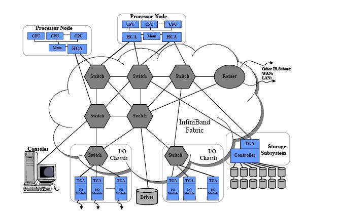
Links are 8B/10B encoded, meaning they carry 8B of data for every 10B transmitted. So Serial Data Rate Infiniband which operates at 2.5 GBps signalling provides 2Gbps of actual data transmission. Data can be sent in the form of 5 message types t0/from a host channel adapter (HCA) at the processor to/from a taget channel adapter (TCA) at a peripheral I/O element. Between the two adapters, messages traverse Infiniband switches and descend to network layer routers if necessary to get to other subnets. The data messages are comprised of packets. A data message must take one of the forms accepted by queue pairs.
An example of an Infiniband network is shown below.
Unlike switches which forward based only on the Local Route Header (LRH), routers read the Global Route Header to forward messages to the correct subnet. Once at the appropriate subnet, the router rebuilds each packet in the message with the appropriate Local Identifier (LID). The standard Infiniband data packet header order is defined as follows:
LRH - Local Route Header
GRH - Global Route Header
BTH - Base Transport Header
ExTH - Extended Transport Header
Msg Payload - Message Payload
Immediate Data Header
I-CRC - Invariant CRC (32-bit)
Not used for Raw datagram
V-CRC - Variant CRC (16-bit)
The local route header is added to data to be sent to another end users within a subnet, this form of communication operates exclusively at the data link layer according to LID in the LRH. There are two types of packets sent in this layer, management and data packets. Management packets deal with link configuration and management while data packets transmit up to a 4KB data payload. The LRH is further defined as follows:
LRH used to route packets within subnets.
VL - Actual Virtual Lane Used
Vers - LRH Version
NH - Next Header - indicates next header
IBA transport, GRH, IPv6 (raw), Ethertype (raw)
SL - Service Level
Destination LID - Destination Local Identifier (unique only within subnet)
Rsv - Reserve Field
Pkt Len - Packet Length
Source LID - Source Local Identifier
The global route headers is added to data to be sent to an end user on another subnet, its header is further defined as follows:
All endnodes are required to source / sink GRH packets
GID (Global Identifier) – valid IPv6 Address
GRH used to route packets between subnets and for multicast
GRH is consistent with IPv6 header per RFC 2460.
TC (Traffic Class) – Communicates end-to-end class of service
Flow ID (Flow Label) – Can be used to identify an end-end flow
Present in all packets if the LRH Next Header = GRH.
Each end node shall be assigned an unique GID
Applications target an end node by its GID
As far as processor efficiency and performance of supercomputer interconnects, Infiniband ranks as the best according to Top500. While Ethernet remains atop the most implemented list due to small scale networks not needing speed as much as low cost scalability in an interconnect, Infiniband is taking a larger portion of the market due to its high performance specs.
Infiniband DDR
On the physical layer, Infiniband defines three link speeds, 1x, 4x and 12x. Each link has four wires (two in each direction) that provide full duplex at 2.5Gbps due to a 2.5Gbps signalling rate for Infiniband SDR.
In InfiniBand DDR (Double Data Rate), the signalling rate is increased to 5 Gbits/s, giving a 4x link 16 Gbps data throughput since 10B/8B encoded links can be bonded together for additional bandwidth, and 12x links get a 48 Gbps data throughput, at full duplex. Quad data rate (QDR), demonstrated in 2007 with system production expected in 2008, have a signalling rate of 10 Gbps per lane and can acheive 96 Gbps data throughput on a 12x 10B/8B encoded link.
Myrinet
While IBM's Federation, SGI's NUMAlink and other interconnects are internal physical layer switch topologies built for a particular supercomputer type, Myrinet, like Ethernet and Infiniband, brings a broad network compatability approach to connect supercomputer clusters.
Myrinet is a data link layer interconnect developed by Myricom to replace Ethernet. It can connect clusters of computers and provides 5-10 times lower latency than Ethernet over TCP/IP. It uses a 2.5 Gbit/s link that provides processor offload. It uses lightweight protocols capable of providing more throughput, less interference and latency than Ethernet. Myricom has developed an array of programs to operate on Myrinet interconnects, allowing the host CPU to bypass the operating system in the upper application layers for further reductions in latency. Myrinet packets include a header, payload, and CRC bits.
The setup for a Myrinet network is arranged as follows:
Pros/Cons
While Myrinet is a valid interconnect still used in some supercomputer networks, the battle for performance and implementation superiority is obviously between Ethernet and Infiniband. The pros and cons of Ethernet's bus based topology vs. Infiniband's switch based topology are shown in the following table:
One drawback to Infiniband is its lack of a formal programming interface standard. While Ethernet is defined by IEEE Standard 802.3, the closest interface standard for Infiniband is the OpenFabrics Alliance verb list which has been adopted by most of the corporate sponsors of Infiniband.
Infiniband has impacted the supercomputer interconnect market so quickly due to its high bandwidth and low latency (200ns) connectivity which has made it the preferred choice for connecting computer nodes into a cluster. The interconnect comparison in the general marketplace continues to be dominated by Ethernet because of its ability to connect other resources, such as remote sites and users’ desktops due to its broad availability and formal standards.
Sources
[1] top500.org interconnect usage (Share %), performance statistics (Rmax Sum)
[2]IEEE 802.3 Ethernet Standard
[3] Ethernet protocol summary on Wikipedia
[4] Myrinet article
[5] Dr. Steve Hunter on Infiniband, NCSU Architecture of Parallel Computers, Lecture 12, 6/12/2006
[6] RTC Magazine, Processor Efficiency chart
[7] Myrinet open source protocol
[8] IBTA Whitepapers: Intro to Infiniband
[9] IBTA Whitepapers: Enhanced Reliability
