CSC/ECE 506 Spring 2013/12a cm: Difference between revisions
No edit summary |
No edit summary |
||
| (26 intermediate revisions by 2 users not shown) | |||
| Line 4: | Line 4: | ||
In a multi-processor system, processors need to communicate with each other and access each other's resources. In order to route data and messages between processors, an interconnection architecture is needed. | In a multi-processor system, processors need to communicate with each other and access each other's resources. In order to route data and messages between processors, an interconnection architecture is needed. | ||
</p> | </p> | ||
<p> | <p> | ||
Typically, in a multiprocessor system, message passed between processors are frequent and short<sup>1</sup>. Therefore, the interconnection network architecture must handle messages quickly by having '''low latency''', and must handle several messages at a time and have '''high bandwidth'''. | Typically, in a multiprocessor system, message passed between processors are frequent and short<sup><span id="1body">[[#1foot|[1]]]</span></sup>. Therefore, the interconnection network architecture must handle messages quickly by having '''low latency''', and must handle several messages at a time and have '''high bandwidth'''. | ||
</p> | </p> | ||
<p> | <p> | ||
| Line 19: | Line 15: | ||
<h1>History of Network Topologies</h1> | <h1>History of Network Topologies</h1> | ||
Hypercube topologies were invented in the 80s and had desirable characteristics when the number of nodes is small (~1000 maximum, often <100) and every processor must stop working to receive and forward the message <sup>4</sup>. The low-radix era began in 1985 and was defined by routers with between 4 and 8 ports using toroidal, mesh or fat-tree topologies and wormhole routing. This era lasted about 20 years until it was determined that routers with dozens of ports offered superior performance. Two topologies were developed to take advantage of the newly developed high-radix routers. These are flattened butterfly and dragonfly, which are somewhere between a mesh with each point on the mesh being a router (or virtual router in the case of dragonfly) with dozens or hundreds of nodes attached and a fat tree with sufficiently high arity as to only have two levels. | Hypercube topologies were invented in the 80s and had desirable characteristics when the number of nodes is small (~1000 maximum, often <100) and every processor must stop working to receive and forward the message <sup><span id="4body">[[#4foot|[4]]]</span></sup>. The low-radix era began in 1985 and was defined by routers with between 4 and 8 ports using toroidal, mesh or fat-tree topologies and wormhole routing. This era lasted about 20 years until it was determined that routers with dozens of ports offered superior performance. Two topologies were developed to take advantage of the newly developed high-radix routers. These are flattened butterfly and dragonfly, which are somewhere between a mesh with each point on the mesh being a router (or virtual router in the case of dragonfly) with dozens or hundreds of nodes attached and a fat tree with sufficiently high arity as to only have two levels. | ||
The use of different topologies has changed over the years. The following pie charts from top500.org show the share of different network topologies over the years. | |||
[[Image:ob_wiki_12_2001.png ]] ''Interconnect Family Market Share for 2001'' | |||
[[Image:ob_wiki_12_2004.png]] ''Interconnect Family Market Share for 2004'' | |||
[[Image:ob_wiki_12_2007.png]] ''Interconnect Family Market Share for 2007'' | |||
[[Image:ob_wiki_12_2010.png]] ''Interconnect Family Market Share for 2010'' | |||
<h1> Performance Metrics for Interconnection Network Topologies</h1> | |||
<p> | |||
The several metrics used for evaluating characteristics of a network topology like latency, bandwidth, cost, etc. are as follows: | |||
*Diameter: This is the longest distance between any pair of nodes of the network. It is measured in terms of network hops (the number of links the message must travel before reaching the destination). | |||
*Bisection Bandwidth: This is the minimum number of links that one must cut in order to partition the network into two halves. | |||
*Degree: This is the total number of links in and out from a router. | |||
</p> | |||
<p> | |||
The Diameter and Bisection bandwidth are the measure of performance of a network while the degree along with the total number of links is the measure of cost. | |||
</p> | |||
<h2>Interconnection evolution in the Top500 List</h2> | <h2>Interconnection evolution in the Top500 List</h2> | ||
[[Image:Top500interconnect.png|thumbnail|300px|left|]] | [[Image:Top500interconnect.png|thumbnail|300px|left|]] | ||
This chart shows the evolution over time of the different interconnect topologies by their dominance in the top500 list of supercomputers <sup>7</sup>. As one can see, many technologies came into vogue briefly before losing performance share and disappearing. In the early days of the list, most of the computers list that the interconnect type is not applicable. However, the trailing end of the hypercube phase is clear in burnt orange. The dark blue at the top is "other" and the dark red in the middle is "proprietary", so we can only speculate about what topologies they might employ. The toroidal mesh appears briefly at the start in a cream color, and slightly outlasts the hypercube. The two crossbar technologies (blue and olive) followed the toroidal mesh. The fully-distributed crossbar died out quickly, but the multi-stage crossbar lasted longer but wasn't ever dominant. The 3-D torus (purple) dominates much of the 90s with hypercube topologies (dark pink) enjoying a short comeback in the later part of the decade. SP Switch (light olive), an IBM interconnect technology which uses a multi-stage crossbar switch replaced the 3-D torus<sup>8</sup>. Myrinet, Quadrics, and Federation all shared the spotlight in the mid 00s each used a similar fat-tree topology<sup>9 | This chart shows the evolution over time of the different interconnect topologies by their dominance in the top500 list of supercomputers <sup><span id="7body">[[#7foot|[7]]]</span></sup>. As one can see, many technologies came into vogue briefly before losing performance share and disappearing. In the early days of the list, most of the computers list that the interconnect type is not applicable. However, the trailing end of the hypercube phase is clear in burnt orange. The dark blue at the top is "other" and the dark red in the middle is "proprietary", so we can only speculate about what topologies they might employ. The toroidal mesh appears briefly at the start in a cream color, and slightly outlasts the hypercube. The two crossbar technologies (blue and olive) followed the toroidal mesh. The fully-distributed crossbar died out quickly, but the multi-stage crossbar lasted longer but wasn't ever dominant. The 3-D torus (purple) dominates much of the 90s with hypercube topologies (dark pink) enjoying a short comeback in the later part of the decade. SP Switch (light olive), an IBM interconnect technology which uses a multi-stage crossbar switch replaced the 3-D torus<sup><span id="8body">[[#8foot|[8]]]</span></sup>. Myrinet, Quadrics, and Federation all shared the spotlight in the mid 00s each used a similar fat-tree topology<sup><span id="9body">[[#9foot|[9]]]</span></sup><sup><span id="10body">[[#10foot|[10]]]</span></sup>. The current class of supercomputers is dominated by nodes connected with either Infiniband or gigabit ethernet. Both can be connected in either a fat-tree or 2-D mesh topology. The primary difference between them is speed. Infiniband is considerably faster per link and allows links to be ganged into groups of 4 or 12. Gigabit ethernet is vastly less expensive, however, and some supercomputer designers have apparently chosen to save money on the interconnect technology in order to allow the use of faster nodes <sup><span id="11body">[[#11foot|[11]]]</span></sup><sup><span id="12body">[[#12foot|[12]]]</span></sup>. | ||
<br> | |||
<br> | |||
<br> | |||
<br> | |||
<br> | |||
<br> | |||
<br> | |||
<br> | |||
<h1>Types of Network Topologies </h1> | |||
Several metrics are normally choose to represent the cost and performance for a certain topology. In this section, degree, number of links, diameter and bisection width will be calculated for each topology. | |||
<h2>Linear Array</h2> | |||
[[Image:Top_linear.jpg|thumbnail|frame|right|]] | |||
The nodes are connected linearly as in an array. This type of topology is simple, however, it does not scale well. | |||
<br> | |||
* ''Diameter:'' p-1 | |||
* ''Bisection BW:'' 1 | |||
* ''# Links:'' p-1 | |||
* ''Degree:'' 2 | |||
<br> | |||
A linear array is the cheapest way to connect a group of nodes together. The number of links and degree of linear array have the smallest value of any topology. However, the draw back of this topology is also obvious: the two end points suffer the longest distance between each other, which makes the diameter p-1. This topology is also not reliable since the bisection bandwidth is 1. | |||
<h2>Ring</h2> | |||
[[Image:Top_ring.jpg|thumbnail|right|]] | |||
Similar structure as the linear array, except, the ending nodes connect to each other, establishing a circular structure. | |||
<br> | |||
* ''Diameter:'' p/2 | |||
* ''Bisection BW:'' 2 | |||
* ''# Links:'' p | |||
* ''Degree:'' 2 | |||
<br> | |||
Compared with the cheapest linear array topology, the ring topology uses least effort (only add one link) to get a relatively big improvement. The longest distance between two nodes is cut into half. And the biseciton bandwidth has increased to 2. | |||
<h2>2-D Mesh</h2> | |||
[[Image:Top_2Dmesh.jpg|thumbnail|right|]] | |||
The 2-D mesh can be thought of as several linear arrays put together to form a 2-dimensional structure. This topology is very suitable for some of the applications such as the ocean application and matrix calculation. | |||
<br> | |||
* ''Diameter:'' 2(sqrt(p)-1) | |||
* ''Bisection BW:'' sqrt(p) | |||
* ''# Links:'' 2sqrt(p)(sqrt(p)-1) | |||
* ''Degree:'' 4 | |||
<br> | <br> | ||
Nodes that are not on the edge have a '''degree''' of 4. To calculate the number of links, add the number of vertical links, sqrt(p)(sqrt(p)-1), to the number of horizontal links, also sqrt(p)(sqrt(p)-1), to get 2sqrt(p)(sqrt(p)-1). The diameter is calculated by the distance between two diagonal nodes which is the sum of 2 edges of length sqrt(p)-1. | |||
<br> | <br> | ||
<h2>2-D Torus</h2> | |||
[[Image:Top_2Dtorus.jpg|thumbnail|right|]] | |||
Similarly as the trick we did from linear array to ring topology, the 2-D torus takes the structure of the 2-D mesh and connects the nodes on the edges. | |||
<br> | <br> | ||
* Diameter sqrt(p)–1 | |||
* Bisection BW 2sqrt(p) | |||
* # Links 2p | |||
* Degree 4 | |||
<br> | |||
With end-around connection, the longest distance has been cut. And the biseciton bandwidth also increased. Of course, the cost from 2-D mesh to 2-D torus almost increased twice. | |||
<br> | |||
<h2>Cube (3-D Mesh)</h2> | |||
[[Image:Top_cube.jpg|thumbnail|right|]] | |||
If we add two more neighbor to each node, we can get a cube. The cube can be thought of as a three-dimensional mesh. | |||
<br> | |||
* ''Diameter:'' 3(p<sup>1/3</sup>-1) --this is the corner-to-corner distance, analogous to the 2-d mesh formula | |||
* ''Bisection BW:'' p<sup>2/3</sup> -- p<sup>1/3</sup> rows of p<sup>1/3</sup> links must be cut to bisect a cube | |||
* ''# Links:'' 3*p<sup>2/3</sup> -- there are p<sup>2/3</sup> links in each of 3 dimensions. | |||
* ''Degree:'' 6 (from the inside nodes) | |||
<br> | |||
<h2>Hypercube</h2> | |||
[[Image:Top_hypercube.jpg|thumbnail|right|Hypercube]] | |||
In the N-dimensional cube, the boundary nodes are normally the one who hurts the performance of entire network. Thus, we can fix it by connecting those broundary nodes together. The hypercube is essentially multiple cubes put together. | |||
<br> | |||
* ''Diameter:'' log<sub>2</sub>(p) | |||
* ''Bisection BW:'' p/2 -- p/2 links run from one N-1 cube to the other. | |||
* ''# Links:'' p/2 * log<sub>2</sub>(p) -- each node has a degree of log<sub>2</sub>(p). Multiply by p nodes and divide by 2 nodes per link. | |||
* ''Degree:'' log<sub>2</sub>(p) | |||
<br> | |||
From the metrics we can see, the diameter and bisection bandwidth are significantly improved for the high order topologies. Each node is numbered with a bitstring that is log<sub>2</sub>(p) bits long. The farthest away node is this bitstring's complement. One bit can be flipped per hop so the diameter is log<sub>2</sub>(p). | |||
<h2>Tree</h2> | |||
[[Image:Top_tree.jpg|thumbnail|right|Tree]] | |||
The tree is a hierarchical structure nodes on the bottom and switching nodes at the upper levels. | |||
<br> | |||
* ''Diameter:'' 2log<sub>2</sub>(p) -- the path from a leaf through the root to the farthest leaf on the other side | |||
* ''Bisection BW:'' 1 -- breaking either link to the root bisects the tree | |||
* ''# Links:'' 2(p-1) -- there are 2 links for each router and there are p routers if p is a power of 2. | |||
* ''Degree:'' 3 -- interior routers have a degree of 3. | |||
<br> | |||
The tree experiences high traffic at the upper levels. Since almost half of the messages need go through the root node, the root of the tree becomes the bottom neck of the tree topology. Also, the other disadvantage of tree topology is that the bisection bandwidth is only 1. | |||
<h2>Fat Tree</h2> | |||
[[Image:Top_fat_tree.jpg|thumbnail|right|Fat Tree]] | |||
In order to improve the performance of the tree topology, the fat tree alleviates the traffic at upper levels by "fattening" up the links at the upper levels. | |||
<br> | |||
* ''Diameter:'' 2log<sub>2</sub>(p) -- same as a regular tree | |||
* ''Bisection BW:'' p/2 -- all links to (one side of) the root must be cut to bisect the tree | |||
* ''# Links:'' plog<sub>2</sub>(p) -- there are p links at each of log<sub>2</sub>(p) levels | |||
* ''Degree:'' p -- the root node has p links through it. | |||
<br> | |||
The fat tree relieved pressure of root node, the biseciton bandwidth has also been increased. | |||
<h2>Butterfly</h2> | |||
[[Image:Top_butterfly.jpg|thumbnail|right|Butterfly]] | |||
<br> | <br> | ||
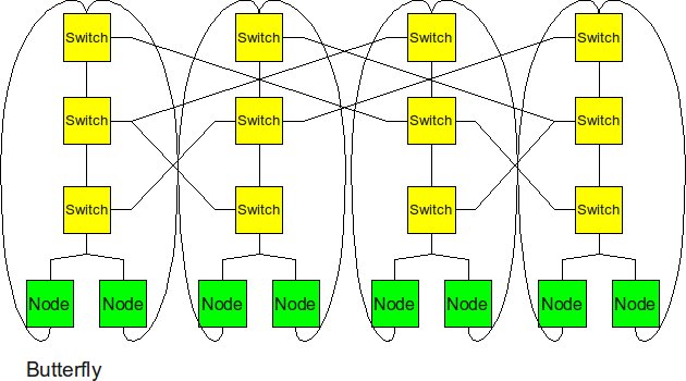
The butterfly structure is similar to the tree structure, but it replicates the switching node structure of the tree topology and connects them together so that there are equal links and routers at all levels. | |||
* ''Diameter:'' 2log<sub>2</sub>(p) -- same as a tree since butterfly has the same depth as a tree (just with p nodes at each level) | |||
* ''Bisection BW:'' p -- p links connect the two halves at the top level | |||
* ''# Links:'' 2p*log<sub>2</sub>(p) -- there are 2*p links at each level times log<sub>2</sub>(p) levels. | |||
* ''Degree:'' 4 -- the routers in the middle levels all have 4 links. The leaves and routers at the top level each have 2 links. | |||
<br> | <br> | ||
Butterfly has similar performance to Hypercube. In terms of cost, butterfly has a smaller degree (so cheaper routers can be used) but hypercube has fewer links. | |||
<h1>Real-World Implementation of Network Topologies </h1> | |||
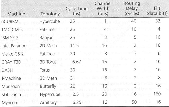
In a research study by Andy Hospodor and Ethan Miller, several network topologies were investigated in a high-performance, high-traffic network<sup><span id="2body">[[#2foot|[2]]]</span></sup>. Several topologies were investigated including the fat tree, butterfly, mesh, torii, and hypercube structures. Advantages and disadvantages including cost, performance, and reliability were discussed. | |||
[[File:Machines.png|frame|center|''Current Machine Statistics''<sup><span id="13body">[[#13foot|[13]]]</span></sup>]] | |||
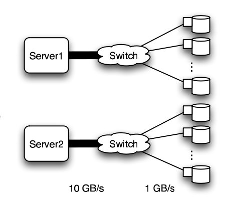
In this experiment, a petabyte-scale network with over 100 GB/s total aggregate bandwidth was investigated. The network consisted of 4096 disks with large servers with routers and switches in between<sup><span id="2body">[[#2foot|[2]]]</span></sup>. | |||
[[Image:Disknet_network.jpg|frame|center|''Basic structure of Hospodor and Miller's experimental network''<sup><span id="2body">[[#2foot|[2]]]</span></sup>]] | |||
The overall structure of the network is shown below. Note that this structure is very susceptible to failure and congestion. | |||
<h2>Fat Tree</h2> | |||
<p> | <p> | ||
1 | In large scale, high performance applications, fat tree can be a choice. However, in order to "fatten" up the links, redundant connections must be used. Instead of using one link between switching nodes, several must be used. The problem with this is that with more input and output links, one would need routers with more input and output ports. Router with an excess of 100 ports are difficult to build and expensive, so multiple routers would have to be stacked together. Still, the routers would be expensive and would require several of them<sup><span id="2body">[[#2foot|[2]]]</span></sup>. | ||
<br> | |||
<br> | |||
The Japan Agency for Marine-Earth Science and Technology supercomputing system uses the fat tree topology. The system connects 1280 processors using NEC processors<sup><span id="7body">[[#7foot|[7]]]</span></sup>. | |||
<br> | |||
Mercury Computer System's RACEway, their original interconnect fabric, uses 6-way crossbar chips organized in a fat tree network. The fat tree network was particularly well suited for Fast Fourier Transforms, which was used for signal processing<sup><span id="13body">[[#13foot|[13]]]</span>. | |||
<h2>Butterfly</h2> | |||
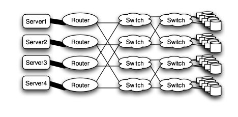
In high performance applications, the butterfly structure is a good choice. The butterfly topology uses fewer links than other topologies, however, each link carries traffic from the entire layer. Fault tolerance is poor. There exists only a single path between pairs of nodes. Should the link break, data cannot be re-routed, and communication is broken<sup><span id="2body">[[#2foot|[2]]]</span></sup>. | |||
[[Image:Disknet_butterfly.jpg|frame|center|''Butterfly structure''<sup><span id="2body">[[#2foot|[2]]]</span></sup>]] | |||
<h2>Meshes and Tori</h2> | |||
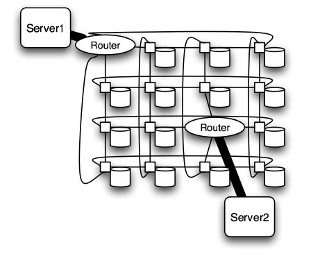
The mesh and torus structure used in this application would require a large number of links and total aggregate of several thousands of ports. However, since there are so many links, the mesh and torus structures provide alternates paths in case of failures<sup><span id="2body">[[#2foot|[2]]]</span></sup>. | |||
[[Image:Disknet_mesh.jpg|frame|center|''Mesh structure''<sup><span id="2body">[[#2foot|[2]]]</span></sup>]] | |||
[[Image:Disknet_torus.jpg|frame|center|''Torus structure''<sup><span id="2body">[[#2foot|[2]]]</span></sup>]] | |||
Some examples of current use of torus structure include the QPACE SFB TR Cluster in Germany using the PowerXCell 8i processors. The systems uses 3-D torus topology with 4608 processors<sup><span id="7body">[[#7foot|[7]]]</span></sup>. | |||
Originally developed for military applications, wireless mesh networks are now being used in the consumer sector. MIT Media Lab's XO-1 laptop, also known as "OLPC" (One Laptop Per Child) uses mesh networking to create an inexpensive infrastructure. The connections made by the laptops are used to reduce the need for an external infrastructure<sup><span id="15body">[[#15foot|[15]]]</span>. | |||
<h2>Hypercube</h2> | |||
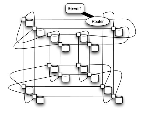
Similar to the torii structures, the hypercube requires larger number of links. However, the bandwidth scales better than mesh and torii structures. | |||
Intel produced several supercomputers using hypercube design, of which the best known was the iPSC/860. Other early supercomputers, including the first few models of the Conection Machine family from Thinking Machines Corporation, also used the hypercube design. The CRAY T3E, CRAY XT3, and SGI Origin 2000 also used k-ary n-cubed topologies. | |||
[[Image:Disknet_hypercube.jpg|frame|center|''Hypercube structure''<sup><span id="2body">[[#2foot|[2]]]</span></sup>]] | |||
It is worth to mention that even though there are many topologies have much better performance than 2-D mesh, the cost of these advanced topologies are also high. Since most of the chips is in 2-D space, it is very expensive to implement high dimensional topology on 2-D chip. For hypercube topology, the increases of number of node will cause higher degree for each node. For the butterfly topology, although the increases of degree is relatively slow but the required number of links and number of switches increases rapidly. | |||
<h1> Why do meshes dominate?</h1> | |||
From the perspective of performance and flexibility for each of the topologies, it looks like higher dimension networks are preferable compared to low dimensional networks. However, in reality, cost of building the network is also an important consideration. A mesh network is much easier to layout because all of the connections can be made in 2 dimensions. Conversely, hypercubes and butterflies contain many crossing wires which may need to be quite long to loop around the edge. | |||
<br> <br> | |||
In a 2D network, each router is very simple since it only needs to have a degree of 4. A router usually uses crossbar switches to route inputs to outputs and the cost of additional ports increase the complexity quadratically. | |||
In comparison to a 2D mesh, a router for a hypercube is much more complex with a degree of twice the diameter. For example, for 5 dimensions, we need a router of degree 10. With other networks like a butterfly, the complexity of a router remains same at 4 but we would need a larger number of routers as the number of links is more. | |||
As an example, IBM's [http://en.wikipedia.org/wiki/Blue_Gene/Q Blue Gene/Q] uses a 3D mesh interconnect with auxiliary networks for global communications (broadcast and reductions), I/O, and management. | |||
<h1>Comparison of Network Topologies </h1> | |||
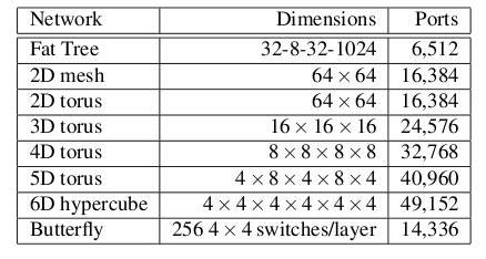
The following table shows the total number of ports required for each network topology. | |||
<br> | |||
<br> | |||
[[Image:Disknet_ports.jpg]] | |||
<br> | |||
''Number of ports for each topology''<sup><span id="2body">[[#2foot|[2]]]</span></sup> | |||
<br> | |||
As the figure above shows, the 6-D hypercube requires the largest number of ports, due to its relatively complex six-dimensional structure. In contrast, the fat tree requires the least number of ports, even though links have been "fattened" up by using redundant links. The butterfly network requires more than twice the number of ports as the fat tree, since it essentially replicates the switching layer of the fat tree. The number of ports for the mesh and torii structures increase as the dimensionality increases. However, with modern router technology, the number of ports is a less important consideration. | |||
<br> | |||
<br> | <br> | ||
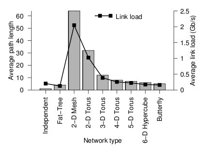
Below the average path length, or average number of hops, and the average link load (GB/s) is shown. | |||
<br> | |||
<br> | |||
[[Image:Disknet_load.jpg]] | |||
<br> | |||
''Average path length and link load for each topology''<sup><span id="2body">[[#2foot|[2]]]</span></sup> | |||
<br> | |||
Looking at the trends, when average path length is high, the average link load is also high. In other words, average path length and average link load are proportionally related. It is obvious from the graph that 2-D mesh has, by far, the worst performance. In a large network such as this, the average path length is just too high, and the average link load suffers. For this type of high-performance network, the 2-D mesh does not scale well. Likewise the 2-D torus cuts the average path length and average link load in half by connected the edge nodes together, however, the performance compared to other types is relatively poor. The butterfly and fat-tree have the least average path length and average link load. | |||
<br> | |||
<br> | |||
The figure below shows the cost of the network topologies. | |||
<br> | |||
<br> | |||
[[Image:Disknet_cost.jpg]] | |||
<br> | |||
''Cost of each topology''<sup><span id="2body">[[#2foot|[2]]]</span></sup> | |||
<br> | |||
Despite using the fewest number of ports, the fat tree topology has the highest cost, by far. Although it uses the fewest ports, the ports are high bandwidth ports of 10 GB/s. Over 2400, ports of 10 GB/s are required have enough bandwidth at the upper levels of the tree. This pushes the cost up dramatically, and from a cost standpoint is impractical. While the total cost of fat tree is about 15 million dollars, the rest of the network topologies are clustered below 4 million dollars. When the dimensionalality of the mesh and torii structures increase, the cost increases. The butterfly network costs between the 2-D mesh/torii and the 6-D hypercube. | |||
<br> | |||
<br> | |||
When the cost and average link load is factored the following graph is produced. | |||
<br> | |||
<br> | |||
[[Image:Disknet_overall.jpg]] | |||
<br> | |||
''Overall cost of each topology''<sup><span id="2body">[[#2foot|[2]]]</span></sup> | |||
<br> | |||
From the figure above, the 6-D hypercube demonstrates the most cost effective choice on this particular network setup. Although the 6-D hypercube costs more because it needs more links and ports, it provides higher bandwidth, which can offset the higher cost. The high dimensional torii also perform well, but cannot provide as much bandwidth as the 6-D hypercube. For systems that do not need as much bandwidth, the high-dimensional torii is also a good choice. The butterfly topology is also an alternative, but has lower fault tolerance. | |||
However, when the number of nodes increases, the relative cost of the higher-dimensional topologies increases far faster than their relative performance when compared to a 2-D mesh. This is because the 2-D mesh only uses low-cost, short links. The higher-dimensional structures must be projected onto our 3-dimensional world, and thus require many long, expensive links that wrap around the outside of the system like an impenetrable tangle of jungle vines. Maintaining such a network is also quite slow and tedious. | |||
<br> | |||
=References= | |||
<span id="1foot">[[#1body|1.]]</span> Y. Solihin, ''Fundamentals of Parallel Computer Architecture''. Madison: OmniPress, 2009. <br> | |||
<span id="2foot">[[#2body|2.]]</span> http://www.ssrc.ucsc.edu/Papers/hospodor-mss04.pdf Interconnection Architectures for Petabyte-Scale High-Performance Storage Systems <br> | |||
<span id="3foot">[[#3body|3.]]</span> http://www.diit.unict.it/~vcatania/COURSES/semm_05-06/DOWNLOAD/noc_routing02.pdf The Odd-Even Turn Model for Adaptive Routing <br> | |||
<span id="4foot">[[#4body|4.]]</span> http://www.csm.ornl.gov/workshops/IAA-IC-Workshop-08/documents/wiki/dally_iaa_workshop_0708.pdf Interconnection Topologies:(Historical Trends and Comparisons <br> | |||
<span id="5foot">[[#5body|5.]]</span> http://dspace.upv.es/xmlui/bitstream/handle/10251/2603/tesisUPV2824.pdf?sequence=1 Efficient mechanisms to provide fault tolerance in interconnection networks for PC clusters, José Miguel Montañana Aliaga. <br> | |||
<span id="6foot">[[#6body|6.]]</span> http://web.ebscohost.com.www.lib.ncsu.edu:2048/ehost/pdfviewer/pdfviewer?vid=2&hid=15&sid=72e3828d-3cb1-42b9-8198-5c1e974ea53f@sessionmgr4 Adaptive Fault Tolerant Routing Algorithm for Tree-Hypercube Multicomputer, Qatawneh Mohammad <br> | |||
<span id="7foot">[[#7body|7.]]</span> http://www.top500.org TOP500 Supercomputing Sites <br> | |||
<span id="8foot">[[#8body|8.]]</span> http://www.redbooks.ibm.com/abstracts/sg245161.html?Open Understanding and Using the SP Switch <br> | |||
<span id="9foot">[[#9body|9.]]</span> http://www.myri.com/myrinet/overview/ Myrinet Overview <br> | |||
<span id="10foot">[[#10body|10.]]</span> http://en.wikipedia.org/wiki/QsNet QsNet (Quadrics' network)<br /> | |||
<span id="11foot">[[#11body|11.]]</span> http://www.google.com/research/pubs/pub35155.html Dragonfly Topology <br /> | |||
<span id="12foot">[[#12body|12.]]</span> http://citeseerx.ist.psu.edu/viewdoc/download?doi=10.1.1.95.573&rep=rep1&type=pdf Flattened Butterfly Topology <br /> | |||
<span id="13foot">[[#13body|13.]]</span> http://courses.engr.illinois.edu/cs533/sp2012/notes/InterconnectionNet.pdf <br /> | |||
<span id="14foot">[[#14body|14.]]</span> http://courses.csail.mit.edu/6.896/spring04/handouts/papers/fat_trees.pdf <br /> | |||
<span id="15foot">[[#15body|15.]]</span> http://wiki.laptop.org/go/Mesh_Network_Details <br /> | |||
<br /> | |||
Latest revision as of 05:06, 25 April 2013
Interconnection Network Architecture
In a multi-processor system, processors need to communicate with each other and access each other's resources. In order to route data and messages between processors, an interconnection architecture is needed.
Typically, in a multiprocessor system, message passed between processors are frequent and short[1]. Therefore, the interconnection network architecture must handle messages quickly by having low latency, and must handle several messages at a time and have high bandwidth.
In a network, a processor along with its cache and memory is considered a node. The physical wires that connect between them is called a link. The device that routes messages between nodes is called a router. The shape of the network, such as the number of links and routers, is called the network topology.
History of Network Topologies
Hypercube topologies were invented in the 80s and had desirable characteristics when the number of nodes is small (~1000 maximum, often <100) and every processor must stop working to receive and forward the message [4]. The low-radix era began in 1985 and was defined by routers with between 4 and 8 ports using toroidal, mesh or fat-tree topologies and wormhole routing. This era lasted about 20 years until it was determined that routers with dozens of ports offered superior performance. Two topologies were developed to take advantage of the newly developed high-radix routers. These are flattened butterfly and dragonfly, which are somewhere between a mesh with each point on the mesh being a router (or virtual router in the case of dragonfly) with dozens or hundreds of nodes attached and a fat tree with sufficiently high arity as to only have two levels.
The use of different topologies has changed over the years. The following pie charts from top500.org show the share of different network topologies over the years.
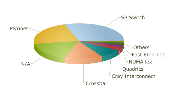 Interconnect Family Market Share for 2001
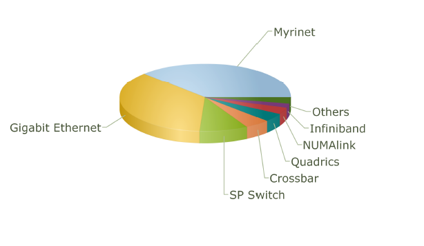 Interconnect Family Market Share for 2004
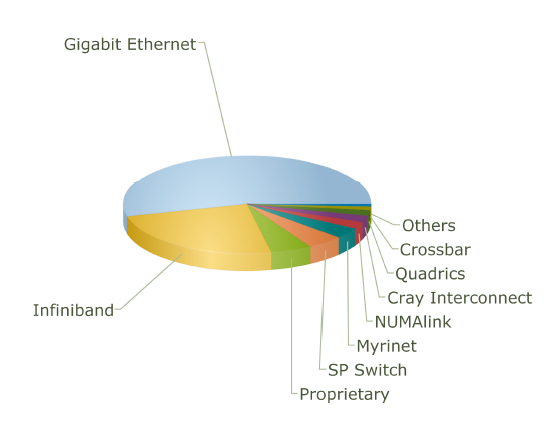 Interconnect Family Market Share for 2007
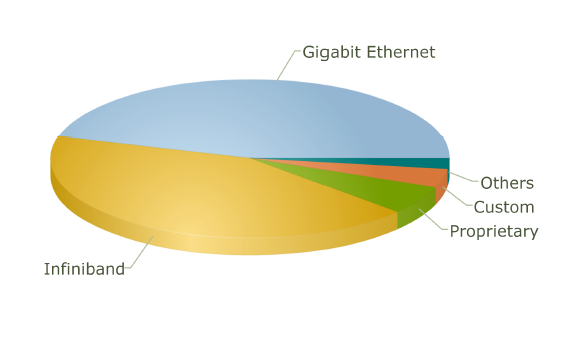 Interconnect Family Market Share for 2010
Performance Metrics for Interconnection Network Topologies
The several metrics used for evaluating characteristics of a network topology like latency, bandwidth, cost, etc. are as follows:
- Diameter: This is the longest distance between any pair of nodes of the network. It is measured in terms of network hops (the number of links the message must travel before reaching the destination).
- Bisection Bandwidth: This is the minimum number of links that one must cut in order to partition the network into two halves.
- Degree: This is the total number of links in and out from a router.
The Diameter and Bisection bandwidth are the measure of performance of a network while the degree along with the total number of links is the measure of cost.
Interconnection evolution in the Top500 List
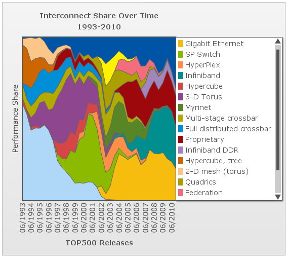
This chart shows the evolution over time of the different interconnect topologies by their dominance in the top500 list of supercomputers [7]. As one can see, many technologies came into vogue briefly before losing performance share and disappearing. In the early days of the list, most of the computers list that the interconnect type is not applicable. However, the trailing end of the hypercube phase is clear in burnt orange. The dark blue at the top is "other" and the dark red in the middle is "proprietary", so we can only speculate about what topologies they might employ. The toroidal mesh appears briefly at the start in a cream color, and slightly outlasts the hypercube. The two crossbar technologies (blue and olive) followed the toroidal mesh. The fully-distributed crossbar died out quickly, but the multi-stage crossbar lasted longer but wasn't ever dominant. The 3-D torus (purple) dominates much of the 90s with hypercube topologies (dark pink) enjoying a short comeback in the later part of the decade. SP Switch (light olive), an IBM interconnect technology which uses a multi-stage crossbar switch replaced the 3-D torus[8]. Myrinet, Quadrics, and Federation all shared the spotlight in the mid 00s each used a similar fat-tree topology[9][10]. The current class of supercomputers is dominated by nodes connected with either Infiniband or gigabit ethernet. Both can be connected in either a fat-tree or 2-D mesh topology. The primary difference between them is speed. Infiniband is considerably faster per link and allows links to be ganged into groups of 4 or 12. Gigabit ethernet is vastly less expensive, however, and some supercomputer designers have apparently chosen to save money on the interconnect technology in order to allow the use of faster nodes [11][12].
Types of Network Topologies
Several metrics are normally choose to represent the cost and performance for a certain topology. In this section, degree, number of links, diameter and bisection width will be calculated for each topology.
Linear Array

The nodes are connected linearly as in an array. This type of topology is simple, however, it does not scale well.
- Diameter: p-1
- Bisection BW: 1
- # Links: p-1
- Degree: 2
A linear array is the cheapest way to connect a group of nodes together. The number of links and degree of linear array have the smallest value of any topology. However, the draw back of this topology is also obvious: the two end points suffer the longest distance between each other, which makes the diameter p-1. This topology is also not reliable since the bisection bandwidth is 1.
Ring
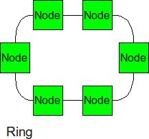
Similar structure as the linear array, except, the ending nodes connect to each other, establishing a circular structure.
- Diameter: p/2
- Bisection BW: 2
- # Links: p
- Degree: 2
Compared with the cheapest linear array topology, the ring topology uses least effort (only add one link) to get a relatively big improvement. The longest distance between two nodes is cut into half. And the biseciton bandwidth has increased to 2.
2-D Mesh
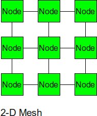
The 2-D mesh can be thought of as several linear arrays put together to form a 2-dimensional structure. This topology is very suitable for some of the applications such as the ocean application and matrix calculation.
- Diameter: 2(sqrt(p)-1)
- Bisection BW: sqrt(p)
- # Links: 2sqrt(p)(sqrt(p)-1)
- Degree: 4
Nodes that are not on the edge have a degree of 4. To calculate the number of links, add the number of vertical links, sqrt(p)(sqrt(p)-1), to the number of horizontal links, also sqrt(p)(sqrt(p)-1), to get 2sqrt(p)(sqrt(p)-1). The diameter is calculated by the distance between two diagonal nodes which is the sum of 2 edges of length sqrt(p)-1.
2-D Torus
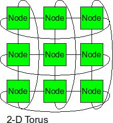
Similarly as the trick we did from linear array to ring topology, the 2-D torus takes the structure of the 2-D mesh and connects the nodes on the edges.
- Diameter sqrt(p)–1
- Bisection BW 2sqrt(p)
- # Links 2p
- Degree 4
With end-around connection, the longest distance has been cut. And the biseciton bandwidth also increased. Of course, the cost from 2-D mesh to 2-D torus almost increased twice.
Cube (3-D Mesh)
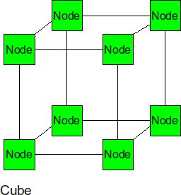
If we add two more neighbor to each node, we can get a cube. The cube can be thought of as a three-dimensional mesh.
- Diameter: 3(p1/3-1) --this is the corner-to-corner distance, analogous to the 2-d mesh formula
- Bisection BW: p2/3 -- p1/3 rows of p1/3 links must be cut to bisect a cube
- # Links: 3*p2/3 -- there are p2/3 links in each of 3 dimensions.
- Degree: 6 (from the inside nodes)
Hypercube
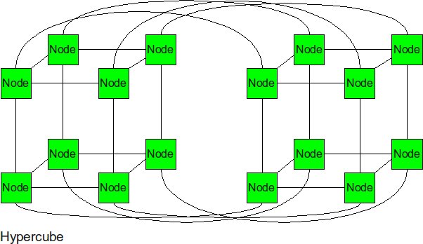
In the N-dimensional cube, the boundary nodes are normally the one who hurts the performance of entire network. Thus, we can fix it by connecting those broundary nodes together. The hypercube is essentially multiple cubes put together.
- Diameter: log2(p)
- Bisection BW: p/2 -- p/2 links run from one N-1 cube to the other.
- # Links: p/2 * log2(p) -- each node has a degree of log2(p). Multiply by p nodes and divide by 2 nodes per link.
- Degree: log2(p)
From the metrics we can see, the diameter and bisection bandwidth are significantly improved for the high order topologies. Each node is numbered with a bitstring that is log2(p) bits long. The farthest away node is this bitstring's complement. One bit can be flipped per hop so the diameter is log2(p).
Tree
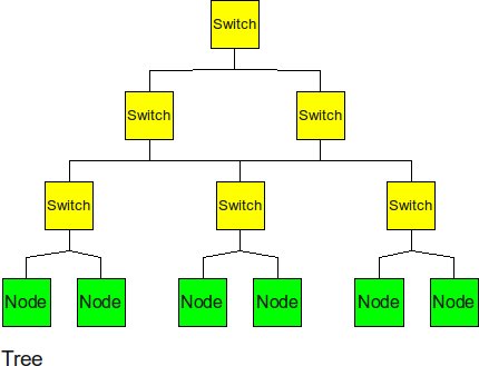
The tree is a hierarchical structure nodes on the bottom and switching nodes at the upper levels.
- Diameter: 2log2(p) -- the path from a leaf through the root to the farthest leaf on the other side
- Bisection BW: 1 -- breaking either link to the root bisects the tree
- # Links: 2(p-1) -- there are 2 links for each router and there are p routers if p is a power of 2.
- Degree: 3 -- interior routers have a degree of 3.
The tree experiences high traffic at the upper levels. Since almost half of the messages need go through the root node, the root of the tree becomes the bottom neck of the tree topology. Also, the other disadvantage of tree topology is that the bisection bandwidth is only 1.
Fat Tree
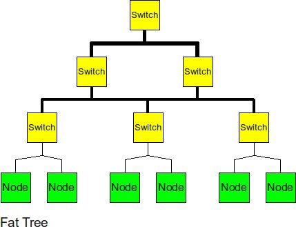
In order to improve the performance of the tree topology, the fat tree alleviates the traffic at upper levels by "fattening" up the links at the upper levels.
- Diameter: 2log2(p) -- same as a regular tree
- Bisection BW: p/2 -- all links to (one side of) the root must be cut to bisect the tree
- # Links: plog2(p) -- there are p links at each of log2(p) levels
- Degree: p -- the root node has p links through it.
The fat tree relieved pressure of root node, the biseciton bandwidth has also been increased.
Butterfly
The butterfly structure is similar to the tree structure, but it replicates the switching node structure of the tree topology and connects them together so that there are equal links and routers at all levels.
- Diameter: 2log2(p) -- same as a tree since butterfly has the same depth as a tree (just with p nodes at each level)
- Bisection BW: p -- p links connect the two halves at the top level
- # Links: 2p*log2(p) -- there are 2*p links at each level times log2(p) levels.
- Degree: 4 -- the routers in the middle levels all have 4 links. The leaves and routers at the top level each have 2 links.
Butterfly has similar performance to Hypercube. In terms of cost, butterfly has a smaller degree (so cheaper routers can be used) but hypercube has fewer links.
Real-World Implementation of Network Topologies
In a research study by Andy Hospodor and Ethan Miller, several network topologies were investigated in a high-performance, high-traffic network[2]. Several topologies were investigated including the fat tree, butterfly, mesh, torii, and hypercube structures. Advantages and disadvantages including cost, performance, and reliability were discussed.
In this experiment, a petabyte-scale network with over 100 GB/s total aggregate bandwidth was investigated. The network consisted of 4096 disks with large servers with routers and switches in between[2].
The overall structure of the network is shown below. Note that this structure is very susceptible to failure and congestion.
Fat Tree
In large scale, high performance applications, fat tree can be a choice. However, in order to "fatten" up the links, redundant connections must be used. Instead of using one link between switching nodes, several must be used. The problem with this is that with more input and output links, one would need routers with more input and output ports. Router with an excess of 100 ports are difficult to build and expensive, so multiple routers would have to be stacked together. Still, the routers would be expensive and would require several of them[2].
The Japan Agency for Marine-Earth Science and Technology supercomputing system uses the fat tree topology. The system connects 1280 processors using NEC processors[7].
Mercury Computer System's RACEway, their original interconnect fabric, uses 6-way crossbar chips organized in a fat tree network. The fat tree network was particularly well suited for Fast Fourier Transforms, which was used for signal processing[13].
Butterfly
In high performance applications, the butterfly structure is a good choice. The butterfly topology uses fewer links than other topologies, however, each link carries traffic from the entire layer. Fault tolerance is poor. There exists only a single path between pairs of nodes. Should the link break, data cannot be re-routed, and communication is broken[2].
Meshes and Tori
The mesh and torus structure used in this application would require a large number of links and total aggregate of several thousands of ports. However, since there are so many links, the mesh and torus structures provide alternates paths in case of failures[2].

Some examples of current use of torus structure include the QPACE SFB TR Cluster in Germany using the PowerXCell 8i processors. The systems uses 3-D torus topology with 4608 processors[7]. Originally developed for military applications, wireless mesh networks are now being used in the consumer sector. MIT Media Lab's XO-1 laptop, also known as "OLPC" (One Laptop Per Child) uses mesh networking to create an inexpensive infrastructure. The connections made by the laptops are used to reduce the need for an external infrastructure[15].
Hypercube
Similar to the torii structures, the hypercube requires larger number of links. However, the bandwidth scales better than mesh and torii structures.
Intel produced several supercomputers using hypercube design, of which the best known was the iPSC/860. Other early supercomputers, including the first few models of the Conection Machine family from Thinking Machines Corporation, also used the hypercube design. The CRAY T3E, CRAY XT3, and SGI Origin 2000 also used k-ary n-cubed topologies.
It is worth to mention that even though there are many topologies have much better performance than 2-D mesh, the cost of these advanced topologies are also high. Since most of the chips is in 2-D space, it is very expensive to implement high dimensional topology on 2-D chip. For hypercube topology, the increases of number of node will cause higher degree for each node. For the butterfly topology, although the increases of degree is relatively slow but the required number of links and number of switches increases rapidly.
Why do meshes dominate?
From the perspective of performance and flexibility for each of the topologies, it looks like higher dimension networks are preferable compared to low dimensional networks. However, in reality, cost of building the network is also an important consideration. A mesh network is much easier to layout because all of the connections can be made in 2 dimensions. Conversely, hypercubes and butterflies contain many crossing wires which may need to be quite long to loop around the edge.
In a 2D network, each router is very simple since it only needs to have a degree of 4. A router usually uses crossbar switches to route inputs to outputs and the cost of additional ports increase the complexity quadratically.
In comparison to a 2D mesh, a router for a hypercube is much more complex with a degree of twice the diameter. For example, for 5 dimensions, we need a router of degree 10. With other networks like a butterfly, the complexity of a router remains same at 4 but we would need a larger number of routers as the number of links is more.
As an example, IBM's Blue Gene/Q uses a 3D mesh interconnect with auxiliary networks for global communications (broadcast and reductions), I/O, and management.
Comparison of Network Topologies
The following table shows the total number of ports required for each network topology.
Number of ports for each topology[2]
As the figure above shows, the 6-D hypercube requires the largest number of ports, due to its relatively complex six-dimensional structure. In contrast, the fat tree requires the least number of ports, even though links have been "fattened" up by using redundant links. The butterfly network requires more than twice the number of ports as the fat tree, since it essentially replicates the switching layer of the fat tree. The number of ports for the mesh and torii structures increase as the dimensionality increases. However, with modern router technology, the number of ports is a less important consideration.
Below the average path length, or average number of hops, and the average link load (GB/s) is shown.
Average path length and link load for each topology[2]
Looking at the trends, when average path length is high, the average link load is also high. In other words, average path length and average link load are proportionally related. It is obvious from the graph that 2-D mesh has, by far, the worst performance. In a large network such as this, the average path length is just too high, and the average link load suffers. For this type of high-performance network, the 2-D mesh does not scale well. Likewise the 2-D torus cuts the average path length and average link load in half by connected the edge nodes together, however, the performance compared to other types is relatively poor. The butterfly and fat-tree have the least average path length and average link load.
The figure below shows the cost of the network topologies.
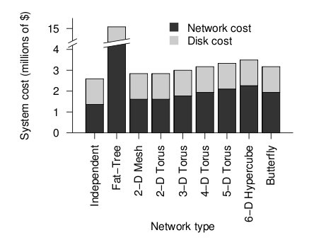
Cost of each topology[2]
Despite using the fewest number of ports, the fat tree topology has the highest cost, by far. Although it uses the fewest ports, the ports are high bandwidth ports of 10 GB/s. Over 2400, ports of 10 GB/s are required have enough bandwidth at the upper levels of the tree. This pushes the cost up dramatically, and from a cost standpoint is impractical. While the total cost of fat tree is about 15 million dollars, the rest of the network topologies are clustered below 4 million dollars. When the dimensionalality of the mesh and torii structures increase, the cost increases. The butterfly network costs between the 2-D mesh/torii and the 6-D hypercube.
When the cost and average link load is factored the following graph is produced.
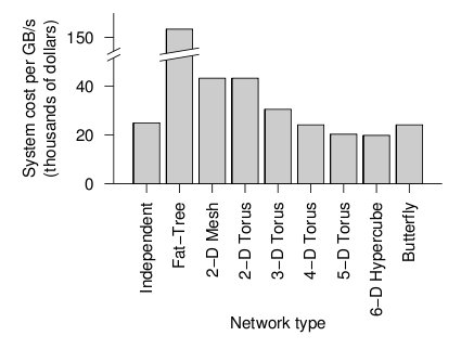
Overall cost of each topology[2]
From the figure above, the 6-D hypercube demonstrates the most cost effective choice on this particular network setup. Although the 6-D hypercube costs more because it needs more links and ports, it provides higher bandwidth, which can offset the higher cost. The high dimensional torii also perform well, but cannot provide as much bandwidth as the 6-D hypercube. For systems that do not need as much bandwidth, the high-dimensional torii is also a good choice. The butterfly topology is also an alternative, but has lower fault tolerance.
However, when the number of nodes increases, the relative cost of the higher-dimensional topologies increases far faster than their relative performance when compared to a 2-D mesh. This is because the 2-D mesh only uses low-cost, short links. The higher-dimensional structures must be projected onto our 3-dimensional world, and thus require many long, expensive links that wrap around the outside of the system like an impenetrable tangle of jungle vines. Maintaining such a network is also quite slow and tedious.
References
1. Y. Solihin, Fundamentals of Parallel Computer Architecture. Madison: OmniPress, 2009.
2. http://www.ssrc.ucsc.edu/Papers/hospodor-mss04.pdf Interconnection Architectures for Petabyte-Scale High-Performance Storage Systems
3. http://www.diit.unict.it/~vcatania/COURSES/semm_05-06/DOWNLOAD/noc_routing02.pdf The Odd-Even Turn Model for Adaptive Routing
4. http://www.csm.ornl.gov/workshops/IAA-IC-Workshop-08/documents/wiki/dally_iaa_workshop_0708.pdf Interconnection Topologies:(Historical Trends and Comparisons
5. http://dspace.upv.es/xmlui/bitstream/handle/10251/2603/tesisUPV2824.pdf?sequence=1 Efficient mechanisms to provide fault tolerance in interconnection networks for PC clusters, José Miguel Montañana Aliaga.
6. http://web.ebscohost.com.www.lib.ncsu.edu:2048/ehost/pdfviewer/pdfviewer?vid=2&hid=15&sid=72e3828d-3cb1-42b9-8198-5c1e974ea53f@sessionmgr4 Adaptive Fault Tolerant Routing Algorithm for Tree-Hypercube Multicomputer, Qatawneh Mohammad
7. http://www.top500.org TOP500 Supercomputing Sites
8. http://www.redbooks.ibm.com/abstracts/sg245161.html?Open Understanding and Using the SP Switch
9. http://www.myri.com/myrinet/overview/ Myrinet Overview
10. http://en.wikipedia.org/wiki/QsNet QsNet (Quadrics' network)
11. http://www.google.com/research/pubs/pub35155.html Dragonfly Topology
12. http://citeseerx.ist.psu.edu/viewdoc/download?doi=10.1.1.95.573&rep=rep1&type=pdf Flattened Butterfly Topology
13. http://courses.engr.illinois.edu/cs533/sp2012/notes/InterconnectionNet.pdf
14. http://courses.csail.mit.edu/6.896/spring04/handouts/papers/fat_trees.pdf
15. http://wiki.laptop.org/go/Mesh_Network_Details