CSC/ECE 506 Spring 2011/ch12 ar: Difference between revisions
No edit summary |
No edit summary |
||
| (One intermediate revision by one other user not shown) | |||
| Line 20: | Line 20: | ||
<p>4.<b> Degree</b> : Number of input/output links connecting to each router is defined as the degree of the network.</p> | <p>4.<b> Degree</b> : Number of input/output links connecting to each router is defined as the degree of the network.</p> | ||
<h1> | <h1>'''Simple Network Topologies''' </h1> | ||
<p>The following network topologies are not widely used in processors, however it is important to discuss these networks because variations of them are used in real machines.</p> | |||
<h2>Linear Array</h2> | <h2>Linear Array</h2> | ||
| Line 41: | Line 42: | ||
In a Ring interconnection network with <b>p</b> nodes, the total number of links in the network would be and the degree of the interconnection network is <b>2</b>. The maximum distance between nodes in the network would be the distance between nodes that are half way through the network, hence the diameter would be <b> p/2 </b>. The bisection bandwidth of the network of the interconnection would thus become 2. | In a Ring interconnection network with <b>p</b> nodes, the total number of links in the network would be and the degree of the interconnection network is <b>2</b>. The maximum distance between nodes in the network would be the distance between nodes that are half way through the network, hence the diameter would be <b> p/2 </b>. The bisection bandwidth of the network of the interconnection would thus become 2. | ||
<h2>2-D | <h2>Cube</h2> | ||
<p> | |||
[[Image:Top_cube.jpg]] | |||
<br> | |||
<br> | |||
The cube can be thought of as a three-dimensional mesh. This topology continues to improve upon the throughput in the 2-D mesh, however the power dissipation will be slightly higher. | |||
</p> | |||
<br> | |||
<h2>Tree</h2> | |||
<p> | <p> | ||
[[Image: | [[Image:Top_tree.jpg]] | ||
<br> | <br> | ||
<br> | <br> | ||
The | The tree has a hierarchical structure of nodes on the bottom and switching nodes at the upper levels. The tree experiences high traffic and high latency if the package must travel through the upper levels. Also because of the high connectivity, this topology has high average energy dissipation.[[#References|<sup>[8]</sup>]] | ||
</p> | </p> | ||
In a | In a k-ary Tree interconnection network with <b>p</b> nodes the degree of the nodes k+1 and the total number of links is k*(p-1). The bisection bandwidth of the network is 1 and the diameter of the network is 2*(log<sub>k</sub>p). | ||
<h2> | <h2>Butterfly</h2> | ||
<p> | <p> | ||
[[Image: | [[Image:Top_butterfly.jpg]] | ||
<br> | <br> | ||
<br> | <br> | ||
The | Another attempt to increase the “skinny” tree structure was the butterfly structure. The butterfly structure is similar to the tree structure, but it replicates the switching node structure of the tree topology and connects them together so that there are equal links and routers at all levels. There are 2 problems with this topology. First of all, there is no path diversity in this topology. There is only one path from the root to a downstream node. This is not ideal incase the network is congested in a certain area, but available in another. There is no way for the network to rebalance the work. Second of all, there are some very long routes in this topology. This requires there to be repeaters in between the nodes, which will cause the physical area to implement the network to increase dramatically. [[#References|<sup>[12]</sup>]] | ||
</p> | </p> | ||
In a butterfly interconnection network topology with <b> p </b>nodes, the degree of the network would be 4 and the total number of links in the network would be 2*p(log<sub>2</sub>p). The diameter of the network is log<sub>2</sub>p. The bisection bandwidth of the network is p/2. | |||
<h1>'''Evolution of Network Topologies''' </h1> | |||
<h2>2-D Mesh</h2> | |||
<p> | |||
[[Image:Top_2Dmesh.jpg]] | |||
<br> | |||
<br> | <br> | ||
The 2-D mesh can be thought of as several linear arrays put together to form a 2-dimensional structure. Nodes that are not on the edge have 4 input or output links, or a '''degree''' of 4. This topology has reasonably low energy dissipation without compromising throughput. The area overhead for this topology is also rather low since a node is never farther than a clock cycle away, this means there is no need for repeater insertion in between the nodes. (the repeaters have a high area overhead, so using them causes the area of the topology to increase) [[#References|<sup>[8]</sup>]] The 2-D mesh topology is one of the first interconnection structures where processors were connected to each other through neighbors. The Soloman machine, which implimented one of the first 2-D mesh topologies, was developed in 1962. In the early designs of these networks they could not perform routing, so the processors had to explicitly relay messages to processors that are not their neighbors. Because of this, these networks had very poor performance.[[#References|<sup>[13]</sup>]] | |||
</p> | |||
In a 2-D Mesh interconnection network with <b> p</b> nodes, the degree of the network would be 4 and the total number of links would be <b> 2*sqrt(p)(sqrt(p) -1) </b>. The diameter of the network would be 2*(sqrt(p) - 1). The bisection bandwidth of the interconnection is the total number of links divided by the diameter of the network, which would result to be sqrt(p). | |||
<h2>Hypercube</h2> | <h2>Hypercube</h2> | ||
| Line 64: | Line 87: | ||
<br> | <br> | ||
<br> | <br> | ||
The hypercube is essentially multiple cubes put together. This topology | The hypercube is essentially multiple cubes put together. This topology became popular in the late 1970’s. The main advantage of this topology is it’s low diameter. [[#References|<sup>[13]</sup>]]Originally there were no routers. The next hops were just programmed into each node. Today the hypercube topology is used by many companies including Intel. It is so attractive because of its small diameter. The nodes are numbered in such a way that every neighboring node is only one bit difference. This greatly increases the ability to route messages through the network. The biggest drawback of the topology is the lack of scalability. For example if the dimension size is increased by one, one link will need to be added to every node in the network. [[#References|<sup>[10]</sup>]] Once the industry reached a limit where it just wasn’t realistic to fit this topology into a package, most designs returned to low dimensional arrays such as 2-D torus. [[#References|<sup>[13]</sup>]] | ||
</p> | </p> | ||
In an interconnection network of <b>p</b> nodes with Hypercube topology, the degree of the network would be log<sub>2</sub>p and the diameter of the network would also be log<sub>2</sub>p. The total number of links in the network would be (p/2)*log<sub>2</sub>p and the bisection bandwidth of the network would be p/2. | In an interconnection network of <b>p</b> nodes with Hypercube topology, the degree of the network would be log<sub>2</sub>p and the diameter of the network would also be log<sub>2</sub>p. The total number of links in the network would be (p/2)*log<sub>2</sub>p and the bisection bandwidth of the network would be p/2. | ||
| Line 74: | Line 97: | ||
<br> | <br> | ||
The 2-D torus takes the structure of the 2-D mesh and connects the nodes on the edges. This decreases the diameter, but the number of links is higher. Thus it slightly improves upon the throughput of the 2-D Mesh, but it also slightly increases the power dissipation relative to the 2-D Mesh since the number of links is higher. The delays on the routes connecting the end nodes together can have an excessively high delays if the topology is not implemented correctly.(printout) This topology was developed in 1985, because of the design constraints, such as pins and bisection, that the hypercube required. [[#References|<sup>[9]</sup>]] | The 2-D torus takes the structure of the 2-D mesh and connects the nodes on the edges. This decreases the diameter, but the number of links is higher. Thus it slightly improves upon the throughput of the 2-D Mesh, but it also slightly increases the power dissipation relative to the 2-D Mesh since the number of links is higher. The delays on the routes connecting the end nodes together can have an excessively high delays if the topology is not implemented correctly.(printout) This topology was developed in 1985, because of the design constraints, such as pins and bisection, that the hypercube required. [[#References|<sup>[9]</sup>]] | ||
</p> | </p> | ||
<br> | <br> | ||
| Line 96: | Line 110: | ||
In an interconnection network with k-ary Fat Tree implementation of <b>p</b> nodes, the degree of the network would be <b>'k+1'</b> and the total number of links would be k*(p-1). The diameter of the network would be 2*log<sub>k</sub>p, the bisection bandwidth of the network would be p/2. | In an interconnection network with k-ary Fat Tree implementation of <b>p</b> nodes, the degree of the network would be <b>'k+1'</b> and the total number of links would be k*(p-1). The diameter of the network would be 2*log<sub>k</sub>p, the bisection bandwidth of the network would be p/2. | ||
<h1>Comparison of Network Topologies </h1> | <h1>Comparison of Network Topologies </h1> | ||
<p> | <p> | ||
The following table shows the total number of ports required for each network topology. | The following table shows the total number of ports required for each network topology. | ||
| Line 269: | Line 274: | ||
<br> | <br> | ||
<p> | <p> | ||
Turns from the y-dimension to the x-dimension are not allowed. | *'''Dimensional ordered (X-Y) routing -''' Turns from the y-dimension to the x-dimension are not allowed. | ||
</p> | </p> | ||
<p> | <p> | ||
Turns to the west are not allowed. | *'''West First -''' Turns to the west are not allowed. | ||
</p> | </p> | ||
<p> | <p> | ||
Turns after a north direction are not allowed. | *'''North Last -''' Turns after a north direction are not allowed. | ||
</p> | </p> | ||
<p> | <p> | ||
Turns in the negative direction (-x or -y) are not allowed, except on the first turn. | *'''Negative First -''' Turns in the negative direction (-x or -y) are not allowed, except on the first turn. | ||
</p> | </p> | ||
<p> | <p> | ||
Unfortunately, the above turn-restriction models reduce the degree of adaptiveness and are partially adaptive. The models cause some packets to take different routes, and not necessarily the minimal paths. This may cause unfairness but reduces the ability of the system to reduce congestion. Overall performance could suffer<sup>3</sup>. | *'''Odd-Even Turn Model -''' Unfortunately, the above turn-restriction models reduce the degree of adaptiveness and are partially adaptive. The models cause some packets to take different routes, and not necessarily the minimal paths. This may cause unfairness but reduces the ability of the system to reduce congestion. Overall performance could suffer<sup>3</sup>. | ||
</p> | </p> | ||
| Line 516: | Line 517: | ||
<br> | <br> | ||
12 [http://books.google.com/books?id=uyAg3zu_DYMC&pg=PA75&lpg=PA75&dq=butterfly+interconnection+network+topology&source=bl&ots=5tQm-TVTu0&sig=oKMwSlpqDJqopnYrKv0BbA8k5uU&hl=en&ei=5cmrTYezINDQiAL9uKjvDA&sa=X&oi=book_result&ct=result&resnum=8&ved=0CFMQ6AEwBw Pros and Cons of the Butterfly Interconnection Network] | 12 [http://books.google.com/books?id=uyAg3zu_DYMC&pg=PA75&lpg=PA75&dq=butterfly+interconnection+network+topology&source=bl&ots=5tQm-TVTu0&sig=oKMwSlpqDJqopnYrKv0BbA8k5uU&hl=en&ei=5cmrTYezINDQiAL9uKjvDA&sa=X&oi=book_result&ct=result&resnum=8&ved=0CFMQ6AEwBw Pros and Cons of the Butterfly Interconnection Network] | ||
<br> | |||
13 [http://books.google.com/books?id=uyAg3zu_DYMC&printsec=frontcover&dq=principles+and+practices+of+interconnection+networks+dally&source=bl&ots=5tQm2YSKp4&sig=3ulQr5DwwSIQQad5VOeAAHs8lLw&hl=en&ei=qhGxTeuKCbPViALx04WwBg&sa=X&oi=book_result&ct=result&resnum=1&sqi=2&ved=0CCQQ6AEwAA#v=onepage&q&f=false Principles and Practices of Interconnection Networks by Dally] | |||
</p> | </p> | ||
<br> | <br> | ||
<br> | <br> | ||
NOTE: This wiki is based off of a [http://pg-server.csc.ncsu.edu/mediawiki/index.php/CSC/ECE_506_Spring_2010/12_EC previous wiki] | NOTE: This wiki is based off of a [http://pg-server.csc.ncsu.edu/mediawiki/index.php/CSC/ECE_506_Spring_2010/12_EC previous wiki] | ||
Latest revision as of 06:45, 22 April 2011
Interconnection Network Architecture
In a mul ti-processor system, processors need to communicate with each other and access each other's resources. In order to route data and messages between processors, an interconnection architecture is needed.
Typically, in a multiprocessor system, message passed between processors are frequent and short1. Therefore, the interconnection network architecture must handle messages quickly by having low latency, and must handle several messages at a time and have high bandwidth. The minimum amount of data that can be transmitted in one cycle is called a phit. A phit is typically determined by to the width of the link. However, data is transferred at the granularity of link-level flow control unit called a flit. A flit worth of data can be accepted or rejected at the receiver, depending on the flow control protocol and amount of buffering available at the receiver.
In a network, a processor along with its cache and memory is considered a node. The physical wires that connect between them is called a link. A link can be unidirectional, in which data can only be sent in one direction, or bidirectional in which data can be sent in both directions. A link, the receiver and sender, make up a channel. The device that routes messages between nodes is called a router. The shape of the network, such as the number of links and routers, is called the network topology.
Various metrics that are to be considered in coming up with a decision on the interconnection networks are the following factors:
1. Diameter : The maximum distance in the network is defined as the diameter. And to compute the average distance, a list of all pairs of nodes is to be made and the average of those would determine the value.
2. Bisection Bandwidth : A network can be partitioned in any number of ways. When a network is divided in such a fashion that it has two equal partitions then the minimum number of links that need to be cut is defined as the Bisection Bandwidth.
3. No. of Links : Number of links in a network is the set of wires that connect two different nodes in the network.
4. Degree : Number of input/output links connecting to each router is defined as the degree of the network.
Simple Network Topologies
The following network topologies are not widely used in processors, however it is important to discuss these networks because variations of them are used in real machines.
Linear Array

The nodes are connected linearly as in an array. This type of topology is simple and low cost. However, it has several shortcoming. First of all, it does not scale well. The longest distance between two nodes, or the diameter, is equivalent to the number of nodes. In addition to not scaling well, this topology can also result in high congestion. [8]
In a linear array interconnection network with p nodes, the total number of links would be p-1 and the degree of the network would be 2 . The total link bandwidth is p-1 times the link bandwidth, but bisection bandwidth is equal to one link bandwidth. Since global communication must always travel through one link, bisection bandwidth summarizes the bandwidth characteristic of the network better than the aggregate bandwidth.
Ring
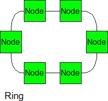
Similar structure as the linear array, except, the ending nodes connect to each other, establishing a circular structure. This topology will scale better since the longest distance between two nodes is cut in half, but it eventually ends up scaling poorly if enough nodes are added. The congestion will also be cut in half since there is now 2 options for packets to traverse.
In a Ring interconnection network with p nodes, the total number of links in the network would be and the degree of the interconnection network is 2. The maximum distance between nodes in the network would be the distance between nodes that are half way through the network, hence the diameter would be p/2 . The bisection bandwidth of the network of the interconnection would thus become 2.
Cube
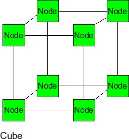
The cube can be thought of as a three-dimensional mesh. This topology continues to improve upon the throughput in the 2-D mesh, however the power dissipation will be slightly higher.
Tree
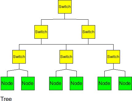
The tree has a hierarchical structure of nodes on the bottom and switching nodes at the upper levels. The tree experiences high traffic and high latency if the package must travel through the upper levels. Also because of the high connectivity, this topology has high average energy dissipation.[8]
In a k-ary Tree interconnection network with p nodes the degree of the nodes k+1 and the total number of links is k*(p-1). The bisection bandwidth of the network is 1 and the diameter of the network is 2*(logkp).
Butterfly
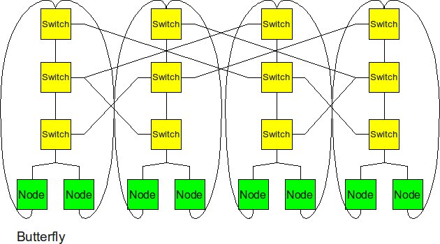
Another attempt to increase the “skinny” tree structure was the butterfly structure. The butterfly structure is similar to the tree structure, but it replicates the switching node structure of the tree topology and connects them together so that there are equal links and routers at all levels. There are 2 problems with this topology. First of all, there is no path diversity in this topology. There is only one path from the root to a downstream node. This is not ideal incase the network is congested in a certain area, but available in another. There is no way for the network to rebalance the work. Second of all, there are some very long routes in this topology. This requires there to be repeaters in between the nodes, which will cause the physical area to implement the network to increase dramatically. [12]
In a butterfly interconnection network topology with p nodes, the degree of the network would be 4 and the total number of links in the network would be 2*p(log2p). The diameter of the network is log2p. The bisection bandwidth of the network is p/2.
Evolution of Network Topologies
2-D Mesh
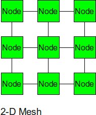
The 2-D mesh can be thought of as several linear arrays put together to form a 2-dimensional structure. Nodes that are not on the edge have 4 input or output links, or a degree of 4. This topology has reasonably low energy dissipation without compromising throughput. The area overhead for this topology is also rather low since a node is never farther than a clock cycle away, this means there is no need for repeater insertion in between the nodes. (the repeaters have a high area overhead, so using them causes the area of the topology to increase) [8] The 2-D mesh topology is one of the first interconnection structures where processors were connected to each other through neighbors. The Soloman machine, which implimented one of the first 2-D mesh topologies, was developed in 1962. In the early designs of these networks they could not perform routing, so the processors had to explicitly relay messages to processors that are not their neighbors. Because of this, these networks had very poor performance.[13]
In a 2-D Mesh interconnection network with p nodes, the degree of the network would be 4 and the total number of links would be 2*sqrt(p)(sqrt(p) -1) . The diameter of the network would be 2*(sqrt(p) - 1). The bisection bandwidth of the interconnection is the total number of links divided by the diameter of the network, which would result to be sqrt(p).
Hypercube
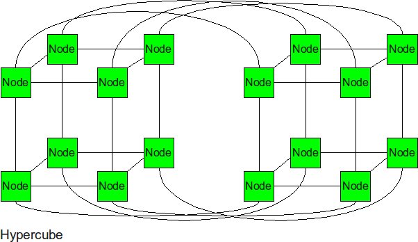
The hypercube is essentially multiple cubes put together. This topology became popular in the late 1970’s. The main advantage of this topology is it’s low diameter. [13]Originally there were no routers. The next hops were just programmed into each node. Today the hypercube topology is used by many companies including Intel. It is so attractive because of its small diameter. The nodes are numbered in such a way that every neighboring node is only one bit difference. This greatly increases the ability to route messages through the network. The biggest drawback of the topology is the lack of scalability. For example if the dimension size is increased by one, one link will need to be added to every node in the network. [10] Once the industry reached a limit where it just wasn’t realistic to fit this topology into a package, most designs returned to low dimensional arrays such as 2-D torus. [13]
In an interconnection network of p nodes with Hypercube topology, the degree of the network would be log2p and the diameter of the network would also be log2p. The total number of links in the network would be (p/2)*log2p and the bisection bandwidth of the network would be p/2.
2-D Torus
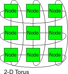
The 2-D torus takes the structure of the 2-D mesh and connects the nodes on the edges. This decreases the diameter, but the number of links is higher. Thus it slightly improves upon the throughput of the 2-D Mesh, but it also slightly increases the power dissipation relative to the 2-D Mesh since the number of links is higher. The delays on the routes connecting the end nodes together can have an excessively high delays if the topology is not implemented correctly.(printout) This topology was developed in 1985, because of the design constraints, such as pins and bisection, that the hypercube required. [9]
Fat Tree
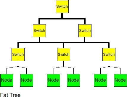
In 1985, an MIT professor invented the fat tree to improve upon the normal “skinny” tree. To improve upon the “skinny” tree topology, the fat tree “fattens” up the links at the upper levels. This helps to alleviate the traffic at upper levels and to decrease the latency of the message. However, by fattening, it is meant that additional links are added to this area, which will increase the average energy dissipated by this topology. [11]
In an interconnection network with k-ary Fat Tree implementation of p nodes, the degree of the network would be 'k+1' and the total number of links would be k*(p-1). The diameter of the network would be 2*logkp, the bisection bandwidth of the network would be p/2.
Comparison of Network Topologies
The following table shows the total number of ports required for each network topology.
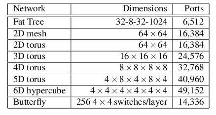
Number of ports for each topology2
As the figure above shows, the 6-D hypercube requires the largest number of ports, due to its relatively complex six-dimensional structure. In contrast, the fat tree requires the least number of ports, even though links have been "fattened" up by using redundant links. The butterfly network requires more than twice the number of ports as the fat tree, since it essentially replicates the switching layer of the fat tree. The number of ports for the mesh and torii structures increase as the dimensionality increases.
Below the average path length, or average number of hops, and the average link load (GB/s) is shown.
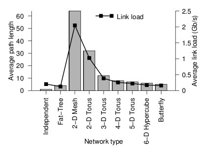
Average path length and link load for each topology2
Looking at the trends, when average path length is high, the average link load is also high. In other words, average path length and average link load are proportionally related. It is obvious from the graph that 2-D mesh has, by far, the worst performance. In a large network such as this, the average path length is just too high, and the average link load suffers. For this type of high-performance network, the 2-D mesh does not scale well. Likewise the 2-D torus cuts the average path length and average link load in half by connected the edge nodes together, however, the performance compared to other types is relatively poor. The butterfly and fat-tree have the least average path length and average link load.
The figure below shows the cost of the network topologies.
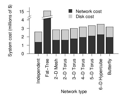
Cost of each topology2
Despite using the fewest number of ports, the fat tree topology has the highest cost, by far. Although it uses the fewest ports, the ports are high bandwidth ports of 10 GB/s. Over 2400, ports of 10 GB/s are required have enough bandwidth at the upper levels of the tree. This pushes the cost up dramatically, and from a cost standpoint is impractical. While the total cost of fat tree is about 15 million dollars, the rest of the network topologies are clustered below 4 million dollars. When the dimensionalality of the mesh and torii structures increase, the cost increases. The butterfly network costs between the 2-D mesh/torii and the 6-D hypercube.
When the cost and average link load is factored the following graph is produced.
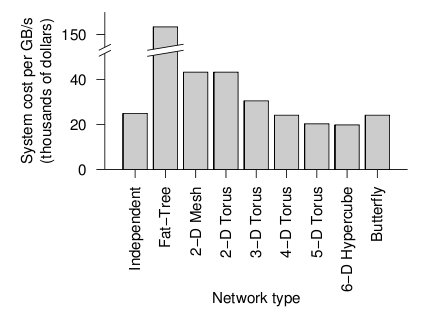
Overall cost of each topology2
From the figure above, the 6-D hypercube demonstrates the most cost effective choice on this particular network setup. Although the 6-D hypercube costs more because it needs more links and ports, it provides higher bandwidth, which can offset the higher cost. The high dimensional torii also perform well, but cannot provide as much bandwidth as the 6-D hypercube. For systems that do not need as much bandwidth, the high-dimensional torii is also a good choice. The butterfly topology is also an alternative, but has lower fault tolerance.
Real-World Implementation of Network Topologies
In a research study by Andy Hospodor and Ethan Miller, several network topologies were investigated in a high-performance, high-traffic network2. Several topologies were investigated including the fat tree, butterfly, mesh, torii, and hypercube structures. Advantages and disadvantages including cost, performance, and reliability were discussed.
In this experiment, a petabyte-scale network with over 100 GB/s total aggregate bandwidth was investigated. The network consisted of 4096 disks with large servers with routers and switches in between2.
The overall structure of the network is shown below. Note that this structure is very susceptible to failure and congestion.
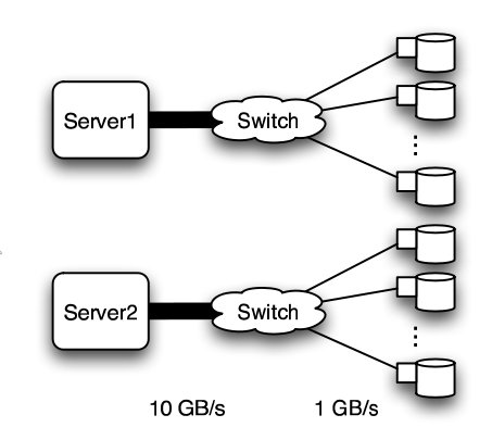
Basic structure of Hospodor and Miller's experimental network2
Fat Tree
In large scale, high performance applications, fat tree can be a choice. However, in order to "fatten" up the links, redundant connections must be used. Instead of using one link between switching nodes, several must be used. The problem with this is that with more input and output links, one would need routers with more input and output ports. Router with excess of 100 ports are difficult to build and expensive, so multiple routers would have to be stacked together. Still, the routers would be expensive and would require several of them2.
The Japan Agency for Marine-Earth Science and Technology supercomputing system uses the fat tree topology. The system connects 1280 processors using NEC processors7.
Butterfly
In high performance applications, the butterfly structure is a good choice. The butterfly topology uses fewer links than other topologies, however, each link carries traffic from the entire layer. Fault tolerance is poor. There exists only a single path between pairs of nodes. Should the link break, data cannot be re-routed, and communication is broken2.
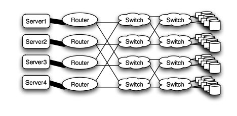
Butterfly structure2
Meshes and Tori
The mesh and torus structure used in this application would require a large number of links and total aggregate of several thousands of ports. However, since there are so many links, the mesh and torus structures provide alternates paths in case of failures2.
Some examples of current use of torus structure include the QPACE SFB TR Cluster in Germany using the PowerXCell 8i processors. The systems uses 3-D torus topology with 4608 processors7.

Mesh structure2
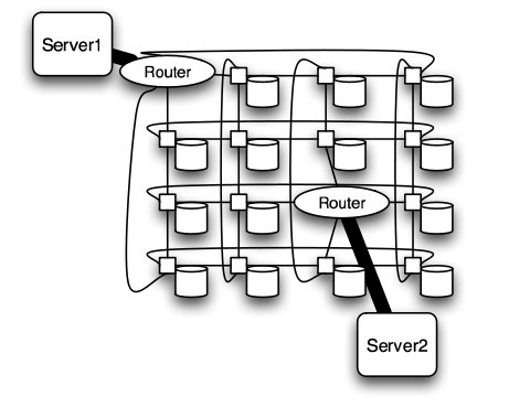
Torus structure2
Hypercube
Similar to the torii structures, the hypercube requires larger number of links. However, the bandwidth scales better than mesh and torii structures.
The CRAY T3E, CRAY XT3, and SGI Origin 2000 use k-ary n-cubed topologies.
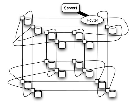
Hypercube structure2
Routing
The routing algorithm determines what path a packet of data will take from source to destination. Routing can be deterministic, where the path is the same given a source and destination, or adaptive, where the path can change. The routing algorithm can also be partially adaptive where packets have multiple choices, but does not allow all packets to use the shortest path3.
Deadlock
When packets are in deadlock when they cannot continue to move through the nodes. The illustration below demonstrates this event.
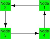
Example of deadlock
Assume that all of the buffers are full at each node. Packet from Node 1 cannot continue to Node 2. The packet from Node 2 cannot continue to Node 3, and so on. Since packet cannot move, it is deadlocked.
The deadlock occurs from cyclic pattern of routing. To avoid deadlock, avoid circular routing pattern.
To avoid circular patterns of routing, some routing patterns are disallowed. These are called turn restrictions, where some turns are not allowed in order to avoid making a circular routing pattern. Some of these turn restrictions are mentioned below.
- Dimensional ordered (X-Y) routing - Turns from the y-dimension to the x-dimension are not allowed.
- West First - Turns to the west are not allowed.
- North Last - Turns after a north direction are not allowed.
- Negative First - Turns in the negative direction (-x or -y) are not allowed, except on the first turn.
- Odd-Even Turn Model - Unfortunately, the above turn-restriction models reduce the degree of adaptiveness and are partially adaptive. The models cause some packets to take different routes, and not necessarily the minimal paths. This may cause unfairness but reduces the ability of the system to reduce congestion. Overall performance could suffer3.
Ge-Ming Chiu introduces the Odd-Even turn model as an adaptive turn restriction, deadlock-free model that has better performance than the previously mentioned models3. The model is designed primarily for 2-D meshes.
Turns from the east to north direction from any node on an even column are not allowed.
Turns from the north to west direction from any node on an odd column are not allowed.
Turns from the east to south direction from any node on an even column are not allowed.
Turns from the south to west direction from any node on an odd column are not allowed.
The illustration below shows allowed routing for different source and destination nodes. Depending on which column the packet is in, only certain directions are allowed.
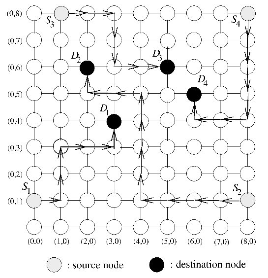
Odd-Even turn restriction model proposed by Ge-Ming Chiu3
Comparison of Turn Restriction Models
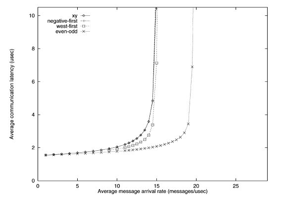
To simulate the performance of various turn restriction models, Chiu simulated a 15 x 15 mesh under various traffic patterns. All channels have bandwidth of 20 flits/usec and has a buffer size of one flit. The dimension-ordered x-y routing, west-first, and negative-first models were compared against the odd-even model.
Traffic patterns including uniform, transpose, and hot spot were conducted. Uniform simulates one node send messages to any other node with equal probability. Transpose simulates two opposite nodes sending messages to their respective halves of the mesh. Hot spot simulates a few "hot spot" nodes that receive high traffic.
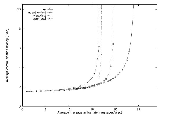
Uniform traffic simulation of various turn restriction models3
The performance of the different routing algorithms is shown above for the uniform traffic. For uniform traffic, the dimensional ordered x-y model outperforms the rest of the models. As the number of messages increase, the x-y model has the "slowest" increase in average communication latency.
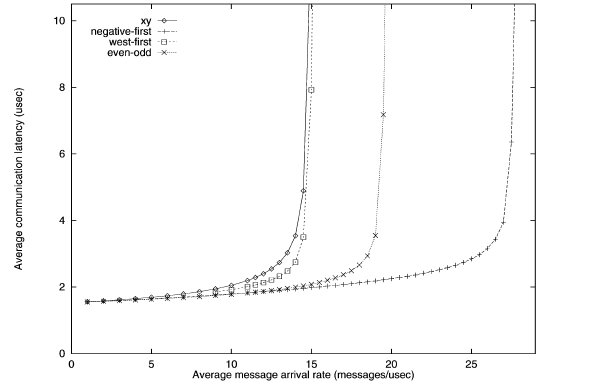
First transpose traffic simulation of various turn restriction models3
The performance of the different routing algorithms is shown above for the first transpose traffic. The negative-first model has the best performance, while the odd-even model performs better than the west-first and x-y models.
Second transpose traffic simulation of various turn restriction models3
With the second transpose simulation, the odd-even model outperforms the rest.
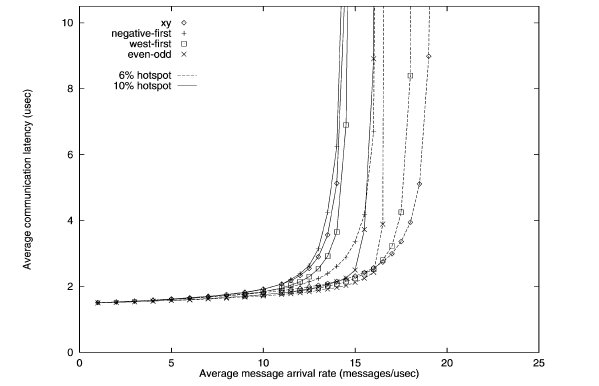
Hotspot traffic simulation of various turn restriction models3
The performance of the different routing algorithms is shown above for the hotspot traffic. Only one hotspot was simulated for this test. The performance of the odd-even model outperforms other models when hotspot traffic is 10%.
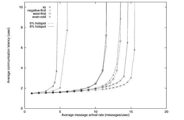
Second hotspot traffic simulation of various turn restriction models3
When the number of hotspots is increased to five, the performance of the odd-even begins to shine. The latency is lowest for both 6 and 8 percent hotspot. Meanwhile, the performance of x-y model is horrendous.
While the x-y model performs well in uniform traffic, it lacks adaptiveness. When traffic becomes hotspot, the x-y model suffers from the inability to adapt and re-route traffic to avoid the congestion caused by hotspots. The odd-even model has superior adaptiveness under high congestion.
Router Architecture
The router is a device that routes incoming data to its destination. It does this by having several input ports and several output ports. Data incoming from one of the inputs ports is routed to one of the output ports. Which output port is chosen depends on the destination of the data, and the routing algorithms.
The internal architecture of a router consists of input and output ports and a crossbar switch. The crossbar switch connects the selects which output should be selected, acting essentially as a multiplexer.
Router technology has improved significantly over the years. This has allowed networks with high dimensionality to become feasible. As shown in the real-world example above, high dimensional torii and hypercube are excellent choice of topology for high-performance networks. The cost of high-performance, high-radix routers has contributed to the viability of these types of high dimensionality networks. As the graph below shows, the bandwidth of routers has improved tremendously over a period of 10 years4.
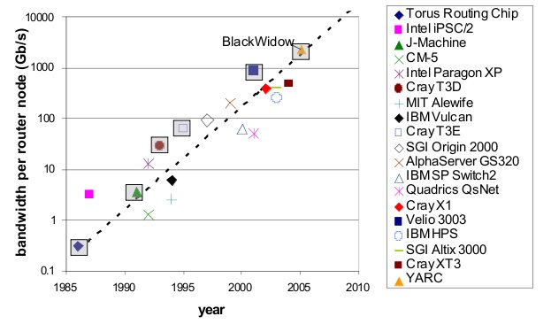
Bandwidth of various routers over 10 year period4
Looking at the physical architecture and layout of router, it is evident that the circuitry has been dramatically more dense and complex.
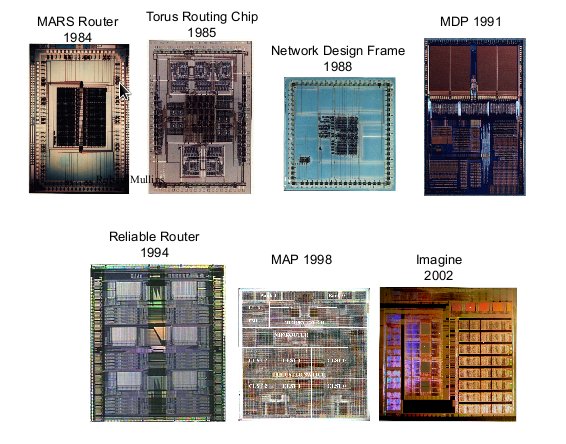
Router hardware over period of time4
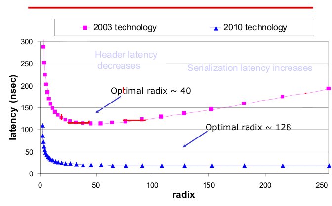
Radix and latency of routers over 10 year period4
The radix, or the number of ports of routers has also increased. The current technology not only has high radix, but also low latency compared to last generation. As radix increases, the latency remains steady.
With high-performance routers, complex topologies are possible. As the router technology improves, more complex, high-dimensionality topologies are possible.
Fault Tolerant Routing
Fault-tolerant routing means the successful routing of messages between any pair of non faulty nodes in the presence of faulty components6. With increased number of processors in a multiprocessor system and high data rates reliable transmission of data in event of network fault is of great concern and hence fault tolerant routing algorithms are important.
Fault Models
Faults in a network can be categorized in two types:
1.Transient Faults5 : A transient fault is a temporary fault that occurs for a very short duration of time. This fault can be caused due to change in output of flip-flop leading to generation of invalid header. These faults can be minimized using error controlled coding. These errors are generally evaluated in terms of Bit Error Rate.
2.Permanent Faults5: A permanent fault is a fault that does not go away and causes a permanent damage to the network. This fault could be due to damaged wires and associated circuitry. These faults are generally evaluated in terms of Mean Time between Failures.
Fault Tolerance Mechanisms (for permanent faults)
The permanent faults can be handled using one of the two mechanisms:
1.Static Mechanism: In static fault tolerance model, once the fault is detected all the processes running in the system are stopped and the routing tables are emptied. Based on the information of faults the routing tables are re-calculated to provide a fault free path.
2.Dynamic Mechanisms: In dynamic fault tolerance model, it is made sure that the operation of the processes in the network is not completely stalled and only the affected regions are provided cure. Some of the methods to do this are:
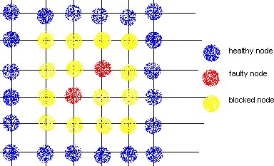
a.Block Faults: In this method many of the healthy nodes in vicinity of the faulty nodes are marked as faulty nodes so that no routes are created close to the actual faulty nodes. The shape of the region could be convex or non-convex, and is made sure that none of the new routes introduce cyclic dependency in the cyclic dependency graph (CDG).
DISADVANTAGE: This method causes lot of healthy nodes to be declared as faulty leading to reduction in system capacity.
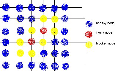
b.Fault Rings: This method was introduced by Chalasani and Boppana. A fault tolerant ring is a set of nodes and links that are adjunct to faulty nodes/links. This approach reduces the number of healthy nodes to be marked as faulty and blocking them.
References
1 Solihin text
2 Interconnection Architectures for Petabyte-Scale High-Performance Storage Systems
3 The Odd-Even Turn Model for Adaptive Routing
4 Interconnection Topologies:(Historical Trends and Comparisons)
5 Efficient mechanisms to provide fault tolerance in interconnection networks for PC clusters, José Miguel Montañana Aliaga.
6 Adaptive Fault Tolerant Routing Algorithm for Tree-Hypercube Multicomputer, Qatawneh Mohammad
7 TOP500 Supercomputing Sites
8 Interconnection Network Topology Tradeoffs
9 Evolution of Interconnection Networks
10 Hypercube pros and cons
11 History of the Fat Tree Topology
12 Pros and Cons of the Butterfly Interconnection Network
13 Principles and Practices of Interconnection Networks by Dally
NOTE: This wiki is based off of a previous wiki