CSC/ECE 517 Fall 2010/ch7 7i sr
Graphical Programming: Why?
The history of computer programming languages is a continuous trend towards ever more powerful abstractions. Languages tend to push complexity into the background, letting the programmer focus primarily on the logic of the application.
While computer science abstractions are extremely useful, applying them in an engineering context can be particularly difficult for the uninitiated. As a way of managing program complexity, a number of companies have developed languages where graphics, rather than words, convey the programmer’s intents to the computer. The power of images as abstractions is obvious in our age of increasing multi-media, and while there are very old (relatively speaking) graphical programming languages, the field is still relatively sparse.
Why this scarcity of graphical languages? We can not say. In our view the chief advantage of a graphical language is program control “lives” in the spatial structure of the code, rather than in the grammar. For grammar-oriented individuals, and those used to programming languages, this may seem a disadvantage, however, for those more visually oriented, the two-dimensional space proffers a richer palette for creating. The following discussion illustrates how various abstractions are implemented in a few graphical languages. The elegant implementations of threading, of programming to interfaces, of refactoring for simplicity, and maintenance of type-correctness are powerful reasons for engineers and computer scientist alike to utilize graphical means for instructing computers.
Languages
In graphical languages there is one Everest, in comparison to which all other contenders are insignificant. Namely National Instruments' LabVIEW. Owing to this immense asymmetry in the industry, almost all the discussion that follows examines LabVIEW's salient characteristics, and a few words are spent on two other graphical programming environment, MathWorks Simulink, and Northwoods Software's Sanscript.
Throughout the web there are numerous definitions of object orientation [1],[2],[3]. In this discussion we hold the perspective that polymorphism, encapsulation, and inheritance (as discussed in the above links) are the core elements of an O-O language or system.
In the following sections we will explore each language described above from the perspective of the salient characteristics necessary for a language to be classified as object-oriented. While some of these are more properly classified as systems rather than languages, evaluating them in context of the O-O languages concepts provides a relevant approach to understanding the benefits and limitations of each tool.
LabVIEW
With little doubt, the dominant force in graphical programming is National Instruments LabVIEW. Developed in 1986 as a tool to communicate with lab instruments, it grew into a full-fledged programming language with extensive capabilities. The examples used in the discussion below are all from a real application.
Data Flow
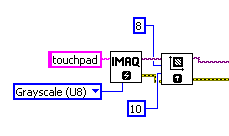
The dominant paradigm in LabVIEW programming is data flow. Unlike most languages where code execution is controlled by sequential commands or callbacks, in LabVIEW data flows along wires, and a code objects only execute when all its inputs receive data values – Figure 1.
Strongly Typed
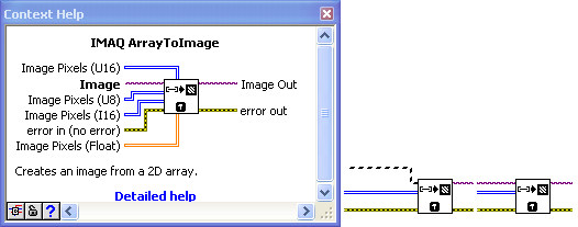
In the above figure, different wires have different colors and texture patterns. LabVIEW is a strongly typed language: each color and texture pattern denotes a different data type. A terminal to a function only accepts wires of the correct type: this property virtual eliminating data-type errors while programming, because a wire is “broken” if it is not connected properly.
Control Structure
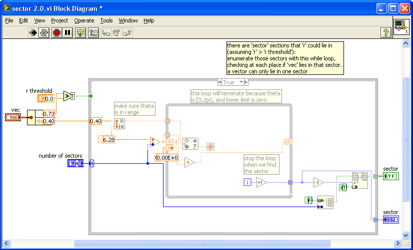
All the major control structures exist in LabVIEW, some taking on multiple forms. A few of the more common ones are shown below.

Programming to Interfaces
In LabVIEW, a function is called a Virtual Instrument, or VI, harking back to the beginnings of the language as an instrument control tool. The advantage of the strongly-typed paradigm is that a function’s interface is automatically documented as soon as the programmer re-factors some functionality into a sub-VI. Each VI has a front panel, which is the function’s interface, and a back panel, which is the function’s implementation. Thus, with no coercion or behavioral training, programmers write code to interfaces rather than implementations.

Debugging
The data flow paradigm automatically structures the code as it is written, regardless of the physical orientation. If you turn on the “highlight execution” option, debugging is trivial, as you can physically see the data flowing. Additionally, if you open a sub-VI, the data going into that sub-VI is shown on the front panel: after the program stops that data is still there, and you can re-run the VI with those values – an especially useful tool in complex applications where a function’s initial conditions are hard to derive.
Encapsulation
Throughout LabVIEW, data is encapsulation by the declaration of the controls and indicators on each VI’s front panel. A control is data that enters a function. An indicator is data that leaves a function. A typedef defines a container of data via a standalone front panel: controls, indicators, and constants may then be instantiated referencing that typedef. A modification to the typedef propagates through the whole application.
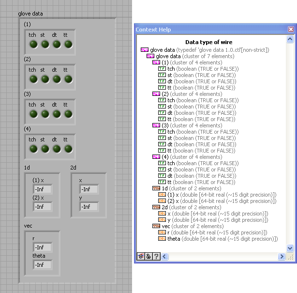
While there are a host of data structures in LabVIEW, the principle ones are highlighted below:
- Numeric: a number, can be integer, double, single, byte, etc.,
- String: the same as in other languages,
- Array: can hold a collection homogenous of objects (including clusters),
- Cluster: a form of a linked list that can hold a heterogeneous collection of other types, including other clusters.
Examples of these data types are shown in Figures 6 and 2 above. Note that in the hierarchy of the data structures, the different data types are identified by their coloration and textures.
Polymorphic
The triangular equal sign in Figure 7 is possibly the best example of LabVIEW’s polymorphic capabilities. The pinkish wires going into the equal sign are of the type shown in Figure 6. The equal block deals with the wires perfectly, despite that five different data types are encapsulated in the pinkish wire!

Multi-Threading
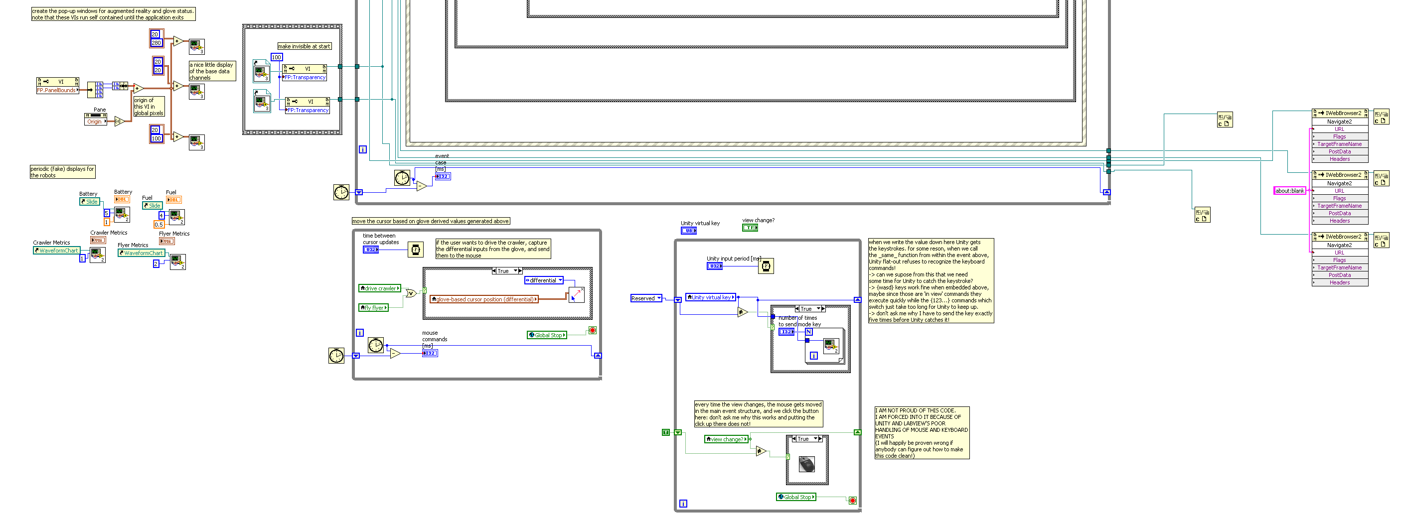
Unlike traditional languages where threading is a difficult concept, in LabVIEW it is trivial. The example below shows a portion of the large application from which all the examples were drawn. There are no less than 10 threads shown. Multiple other’s exist in the application. Various mechanisms for inter-thread communication are used in the application, including polling, broadcasting, global variables, and queuing. Communication method is careful chosen based on program requirements.
Inheritance
To this point we have not talked about inheritance. In general LabVIEW programming, inheritance is not necessary (the authors have never found reason to use it in years of programming), however it is robustly supported. Reference [4] is a fine overview of LabVIEW’s inheritance implementation, while [5] provides an excellent discussion of how LabVIEW’s designers chose their particular approach to inheritance, pass-by-value versus pass-by reference, and a host of other detailed computer-science questions.
Compiled
Unlike many other languages, LabVIEW applications are actually compiled before they are run. When first introduced to the language, one usually suspects it is a scripting language however, as the compilation takes a mere fraction of a second.
Weaknesses
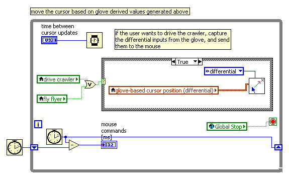
In practice, the primary weakness of LabVIEW’s graphical programming paradigm is by-reference programming. LabVIEW is designed as a value-passing language [5], and thus program clarity suffers when by-reference programming is necessary. An example is shown below. Note that the language still offers by-reference functionality, it is simply harder for the programmer to understand what is happening.
Other Features
The LabVIEW tool suite is exceptional in a number of other ways.
- It is easy to call dynamic libraries from with the language.
- The same LabVIEW code (with certain exceptions) can be target to Windows, Mac, and Linux operating systems. What is more impressive is that the same code can be targeted at a hard real-time operating system, or turned into VHDL and sent to an FPGA.
- By dropping in a special block, LabVIEW can directly execute MATLAB- and C-syntax code, or (using another block) directly call the MATLAB API.
- Because the code is graphical and flows (generally) from left to right, large programs tend to flow off the screen. The programmer's tendency is to keep the code in one screen however. This tendency promotes excellent refactoring practice, as programmers tend to collect sprawling pieces of code and put them into sub-Vis, thus keeping the high-level application clean.
SIMULINK
MathWorks has developed a design environment “Simulink” for simulation, modeling and analyzing Dynamic Systems. Simulink is a graphical block diagramming tool significantly used in DSP and control theory applications. For modeling, Simulink provides a graphical user interface (GUI) for building models as block diagrams, using click-and-drag mouse operations. With this interface, you can draw the models just as you would with pencil and paper (or as most textbooks depict them).
Simulink includes a comprehensive block library of sinks, sources, linear and nonlinear components, and connectors. User defined and custumized blocks can also be created in Simulink.
Features of Simulink
- Component based Modeling.
- User Interface Enhancements.
- Embedded MATLAB.
- Block enhancements.
Object-Oriented Features
Simulink has is similar to an object oriented language. It has a class library with objects defined. It largely implements data type inheritance and even block level inheritance.
However, polymorphism isn't implement in Simulink. But, Simulink.Signal and Simulink.Parameter Objects do obey model Data Type Override Settings.
Although MATLAB SIMULINK is a CASE tool, which is not object-oriented, a function oriented design could be developed, which offers nearly all the possibilities of a classical object-oriented approach.
Example of Simple program in Simulink
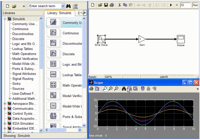
Amplification of a sine wave
Sanscript
San Script is a Graphical Programming Language based on Dataflow Programming. It was developed by Northwoods Software in 1995. Sanscript IDE is broadly divided in three major groups: Overview, Catalog and Canvas. Overview window(on left) displays the list of folders available in Sanscript. These folders are grouped into General (standard function libraries), Examples and Templates (groups of ready-to-run sample programs and sample functions provided in the distribution) and USER (User defined programs). Catalog window (on the bottom) displays the contents of chosen folder: programs and functions. Functions can be dragged into Canvas for further usage, and programs can be clicked for editing. Note that a function can be not only library one but also a user-defined one. Canvas window is the main background which displays the flowgram to be edited.
Features of Sanscript
1. Visual Language
- Has visual Functions with inputs and outputs
- Constant variables
- Links to pass data between functions.
- Repeats / loops.
- Comments (to capture programmers intent)
- Links to remote Connectors (allows deeply nested functions).
- Code regeneration like in Java/C/C++.
2. Rapid Component Creation and Reuse
- Visual Debugging
- Expand function / Replace a constant.
3. Visual Components and Run Time Functionality
- Callout to DLL shared libraries
- Runtime exception handling
4. Editor
- Automatic flow diagram layout
- Zoom in or out : to scale large programs
- Hide-able labels or auto-show them.
Sanscript follows the following paradigm: Imperative, Non- Strict, Scalar, Value-Level, Structured and Visual. It follows a dynamic typing discipline.
Polymorphic
As this language is dynamically typed, we can say that it do show some features of being polymorphism. But it is not so clearly understandable.
Inheritance
Inheritance is implicitly observed as many functions are taken from a group of directories. So they do possess Single inheritance.
Encapsulation
Sanscript being written in C++ / Microsoft Foundation Classes, do demonstrate data hiding behavior. Thus the interdependencies between software components is restricted.
Examples of Programs
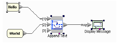
Example 1: Displaying an Message.
Example 2: Repeats/Loops.
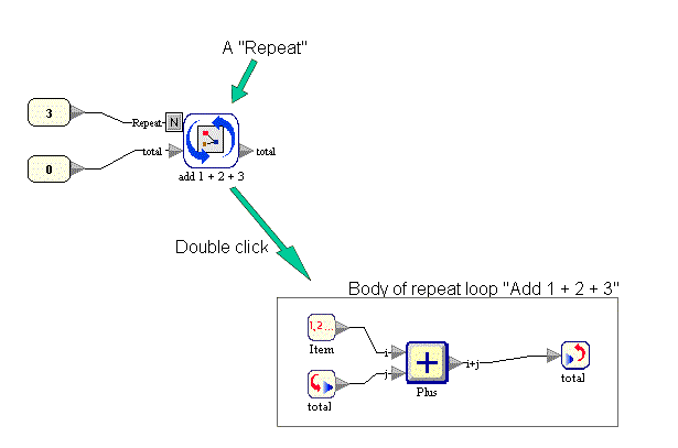
The repeat will execute the loop 3 times, as the item is counted from 1..2..3. The value of total is incremented from 0 to 1 to 3 then finally to 6. The output of the execution will be 6.
References
[1] Object-oriented programming. Retrieved December 10, 2010, from Wikipedia. http://en.wikipedia.org/wiki/Object-oriented_programming
[2] Stroustrup, B. What is “Object-oriented programming”?. 1991. Retrieved December 10, 2010. http://www.scribd.com/doc/21007168/Bjarne-Stroustrup-What-is-Object-Oriented-Programming-Allfreebooks-tk
[3] PC Magazine O-O definition. Retrieved December 10, 2010. http://www.pcmag.com/encyclopedia_term/0,2542,t=object-oriented+programming&i=48238,00.asp
[4] Inheritance in LabVIEW. National Instruments. Retrieved December 10, 2010.: http://zone.ni.com/reference/en-XX/help/371361B-01/lvconcepts/creating_classes/
[5] The decisions behind LabVIEW’s O-O design. National Instruments. Retrieved December 10, 2010. http://zone.ni.com/devzone/cda/tut/p/id/3574
[6] The benefits of programming graphically in NI LabVIEW. National Instruments. Retrieved December 10, 2010. http://www.ni.com/labview/whatis/graphical-programming/
[7] Simulink. The Math Works. Retrieved December 10, 2010. http://www.mathworks.com/help/toolbox/simulink/simulink_product_page.html
[8] Sanscript. Northwoods Software. Retrieved December 10, 2010. http://www.sanscript.net/
[9] Sanscript. Retrieved December 10, 2010. http://progopedia.com/language/sanscript/